
Compared to 4G and previous generations, 5G’s mmWave frequencies and tight integration increase the complexity of both performance and regulator compliance testing.
Many 5G test processes parallel those of 4G LTE, but 5G’s specifications and need for time and cost efficiencies are much more stringent. Designers of user equipment (UE), systems, and networks must account for compliance testing to ensure 5G products meet established guidance. Critical compliance tests include RF exposure, radio testing, and electromagnetic compatibility (EMC).
Testing requirements vary by country and region. Table 1 lists government and industry associations and standards that establish regulatory specifications for 5G devices in relation to testing of the transmitter and receiver.
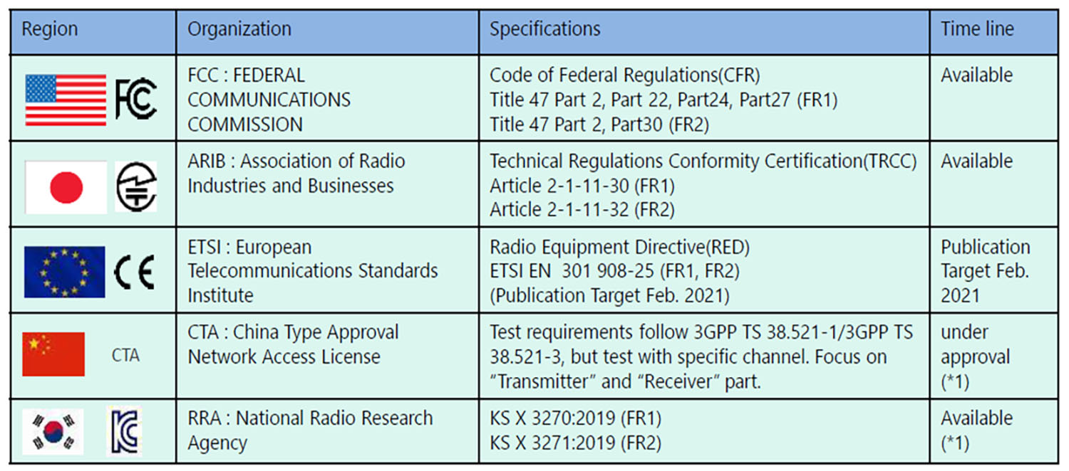
Table 1. Global 5G compliance standards.
These tests differ from established RF exposure measurements that gauge the unintentional generation, propagation, and reception of electromagnetic energy from 5G devices and systems into human tissue. All UE manufacturers and mobile carriers must guarantee product operation that falls within safe parameters for both RF exposure and EMC.
ANSI and IEEE have passed a series of test standards for regulatory compliance. To verify regulatory compliance for EMC and RF exposure, 5G UE manufacturers, system manufacturers, and mobile operators must meet these standards.
RF exposure measurements
RF exposure testing includes absorption and power density. Specific Absorption Rate (SAR) measurements cover UE that utilizes Frequency Range 1 (FR1) sub-6 GHz frequencies. SAR is defined in watts per kilogram of human tissue and measures the rate of RF energy absorbed by the body from the source of RF energy. SAR is a straightforward means to measure the RF exposure characteristics of devices to ensure they are within the Federal Communications Commission (FCC) and other global safety guidelines.
The FCC’s RF exposure standard sets maximum SAR levels well below those used in laboratory testing. SAR levels are also lower than what medical and biological experts believe can cause adverse health effects. The FCC regulates SAR under 47 CFR Part 2, section 2.1093. Products intended for general use must meet a SAR limit of 1.6 mW/g averaged over one gram of tissue in any part of the head or body, and 4 mW/g averaged over 10 grams for hands, wrists, feet, and ankles. Table 2 lists the main parameters that can affect SAR.
| Radio service types (i.e. cellular, PCS, LMR, WLAN) |
| Modulation types (CDMA, GMSK, TDMA, AMPS, etc.) |
| Physical orientation to person (held-to-ear, held-to-face, belt-clip, lap-held, etc.) |
| RF power level (in Watts or milliWatts) |
| Changes to transmitter, antenna (extracted/retracted) or accessories (i.e. clips, batteries) |
Table 2. Parameters that may affect SAR.
Conducting regulatory compliance tests
SAR tests use standardized models of the human head and body filled with liquids that simulate the RF absorption characteristics of different human tissues. Precisely positioned probes measure the RF energy penetrating the models.
To determine compliance, engineers measure emissions from each device while it operates at its highest power level in all operational frequency bands. The established procedure outlined in IEEE C95.1 and IEEE 1528 utilizes a robotic arm system (Figure 1) that performs a series of measurements of the electric field at specific pinpoint locations. It can be a tedious process, due to the robotic movements and multiple measurement points.
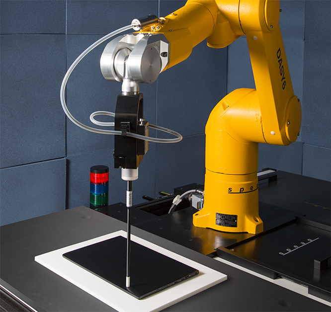
Figure 1. A robotic arm system performs SAR measurements at numerous locations on a device under test.
(Photo courtesy of SPEAG. Schmid & Partner Engineering AG)
An alternative method for these tests gaining adoption is outlined in Technical Standard IEC 62209-3 2019. This approach (Figure 2) utilizes a vector measurement-based system with an array of probes to create a 3D field reconstruction of the wave pattern. This test process takes less time than the robotic method. The method is currently under consideration by the FCC in the United States.
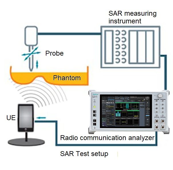
Figure 2. IEC 62209-3 2019 testing makes RF energy measurements using a phantom head.
Power density for mmWave
For UEs that use millimeter wave (mmWave) frequencies — Frequency Range 2 (FR 2) — power-density measurements are the accepted practice. Power density is the amount of power (time rate of energy transfer) per unit volume.
For 5G devices, the dosimetric quantity of the electromagnetic field (EMF) exposure is the incident power density (IPD). To prevent excessive temperature elevation at the body surface, IPD specifies the restrictions on human exposure to EMF at frequencies above 10 GHz. Power density of a transmitting antenna can only be accurately measured in the far-field ̶ farther than two wavelengths from the source.
mmWave test challenges
In a 4G device, you can connect the device to the test instrument using a coaxial cable. Thus, you can evaluate the transceiver and antenna separately. 5G radios, however, use tightly integrated transceivers and antennas due to the introduction of mmWave frequencies and Massive MIMO. Over-the-air (OTA) testing is necessary with the device in an anechoic chamber.
OTA tests include:
- Equivalent, Isotropically Radiated Power (EIRP): tests taken spherically around the device under test (DUT) to gauge the antenna’s effect on radiated power. Isotropic antennas may be used for FR1, but FR2 links require specialized antennas that have additional measurement requirements, adding complexity to the test process.
- Total Radiated Power (TRP): the sum of all radiated power over a 3D sphere surrounding the antenna must be taken.
- Effective Isotropic Sensitivity (EIS): A measurement of sensitivity in a given direction.
- Total Isotropic Sensitivity (TIS): the total available receive performance of a UE is determined by the average sensitivity of an antenna/receiver over a 3D sphere.
OTA testing uses Direct Far Field (DFF) and Indirect Far Field (IFF) measurements. With DFF, the distance between the UE and the antenna approximates the plane wave. The OTA equipment configuration is relatively simple. You can simulate the arrival of signals from certain directions using multiple antennas. Use DFF with known UE antenna sizes.
Use IFF for unknown UE antenna sizes. With IFF, a reflective mirror generates the plane wave, which lets it generate the wave in a shorter distance than DFF. Because the compact antenna test range (CATR) needs a reflector, the configuration is more complex and the equipment more cumbersome than DFF. It’s also impossible to simulate arrival of signals from certain directions/angles.
Smart transmit considerations
An emerging 5G test requirement focuses on Smart Transmit technology now being implemented into chipsets. Smart Transmit gives devices the intelligence to calculate the power required while avoiding high RF exposure. Sometimes referred to as Dynamic Power Control, it also factors the average transmit time, which is an important consideration.
Smart Transmit utilizes time-averaging to monitor and control RF transmit power across multiple antennas. It is especially important due to the number of antennas in a 5G device, as well their frequencies bands, both in mmWave and in sub-6GHz frequency spectrum range.
New regulatory testing will address this type of dynamic power control. Corresponding standards will also establish testing requirements for legacy technologies used by the UE to confirm conformity.
EMC and regulatory test systems
Given the evolving standards by multiple regulatory bodies, engineers need flexible test systems. Flexibility controls cost-of-test because it allows for an efficient upgrade path. Overall, test systems need the following features:
- Advanced, intuitive, and graphical/numerical user interface (UI): Various test parameters and test cases are implemented easily and efficiently with an advanced UI.
- 2D/3D graphing: Antenna characteristics for 5G NR FR2 need to be displayed in 2D/3D graphs. Such views allow results to be intuitively understood.
- Automation test software: a simple GUI to set test conditions and automated Pass/Fail measurement results improve measurement efficiency, while giving engineers greater confidence that the products are in compliance.
- RF test support: test systems must measure key items, such as those in Table 3.
| RF output power (peak power, conducted, and radiated) | Frequency stability |
| Peak and average power spectral density – PAPR limits | Tx adjacent channel leakage power ratio |
| Occupied Bandwidth (OBW | Rx reference sensitivity level |
| Tx/Rx spurious emissions | Rx adjacent channel selectivity (ACS) |
| Tx spectrum emission mask | Rx blocking & intermodulation Characteristics |
Table 3. Typical RF measurements for compliance testing.
Conclusion
RF exposure test processes need to be enacted by UE, system, and network designers, as well as mobile operators to ensure they meet stringent guidelines set forth by industry and government agencies. EMC compliance, while always a test consideration in wireless designs, has become more in focus with 5G’s commercialization. Test environments need to meet current test parameters while still providing a clear and efficient upgrade path as 5G evolves.
 Keyvan Yasami is Market Development Manager for Anritsu with 10+ years in the wireless industry. Keyvan holds a Master’s degree in Electrical Engineering from the University of Maine, and a Business Management degree from Harvard University.