
A microcontroller can communicate with a computer or another device by using a standard method of communication that has been worked out ahead of time. Serial communication is a very common means of communication. Unless you’ve been working in electronics for a while, you might not have a full handle on the plain facts about asynchronous communication.
What is asynchronous serial communication?
Devices using communication send and receive a series of digital pulses between them at a rate that’s been decided upon before communication starts. That agreed-upon signaling is called a protocol. Serial communication initially begins when one device that wishes to communicate sends out data via digital pulses via a serial communication bus (wires) to another device at a rate that the protocol supports. The receiving device picks up the pulses, looking for pulses coming in at the same rate. This type of serial communication is called asynchronous serial communication, where sending and receiving a serial train of pulses does not require a timing clock for both devices to keep everything running at exact times. Instead, both devices keep their timing independent of each other.
Recall that each instruction that’s carried out by a microcontroller (or any other traditional processor) needs a timing clock, kept on pace by a quartz crystal or other regularly pulsing device, to keep instruction cycles running predictably. Asynchronous communication does not require a timing clock that is common to both devices. Each device independently listens and sends digital pulses that represent bits of data at an agreed-upon rate. If both devices can transmit and receive at the same time, it is called full-duplex communication. Half-duplex means that like a walkie-talkie, only one device may communicate at a time and devices take turns transmitting. Sometimes you only need a device that only needs to monitor, or receive, a signal, in which case half-duplex is fine. As another example, if you have a speakerphone where it’s not possible to interrupt the person at the other end, your speakerphone is probably half-duplex.
Asynchronous serial communication is sometimes referred to as Transistor-Transistor Logic (TTL) serial, where the high voltage level is logic 1, and the low voltage equates to logic 0. Almost every microcontroller on the market today has at least one Universal Asynchronous Receiver-Transmitter (UART) for serial communication. All PCs and laptops used to have them a decade or so ago, but serial communication for consumer use has been replaced by Universal Serial Bus (USB). Even so, microcontroller development kits still often use serial communication through a serial port to program the microcontroller using a PC as a host for the programmer. To get around this, USB-to-serial converter cables and drivers are available. FTDI’s USB-to-RS232 level serial UART interface to USB converter is one such product. RS-232 is a well-known serial protocol that was widely used on PCs, is still in wide use, and uses inverted logic.
What do devices need to communicate asynchronously?
To communicate successfully, both devices need to be set up ahead of time regarding some expectations that will enable communication that can be understood on both ends. Besides the data rate for the pulses traveling between devices, the devices need to have in common:
- Both devices must interpret the voltage level of the serial train of pulses in the same way. More specifically, they need to agree on what voltage level represents a bit that is a zero (0) and the voltage level that represents a bit that is a one (1).
- Both must agree as to whether the higher voltage level is a 1 or a 0, or vice versa (which would mean the signal is inverted).
- The devices must share three wires for:
- ground as a common reference point for measuring voltage levels
- sending data, called the transmit line, or transmitter (TX)
- receiving data, called the receiving line, or the receiver (RX)
This might be a good time to point out that a transceiver (XCVR) is a device that combines the ability to both transmit and receive.
The rate at which a serial communication takes place is called a baud rate. Baud rates are measured in bits per second (bps) and some standard baud rates are 110, 300, 600, 1200, 2400, 4800, 9600, 14400, 19200, 28800, 38400, 5600, 57600, 115200, 128000, 153600, 230400, 256000, 460800, and 921600 bps. For simple communication, such as communicating with a microcontroller to program it from a host PC, the baud rate is usually 9600 bps or so. At 9600 baud, a transmitter sends one bit every 1/9600 the of a second and the receiving device will receive at the same rate. Microcontrollers typically sense a high voltage level at +3.3 or +5.0 volts for serial communication. Thus, every 1/9600th of a second, a receiver will look at the line and determine if it’s high or low-level voltage and translate that into a bit or 1 or 0. In TTL series communication, a low voltage level means a 0-bit value and a high voltage level means a 1-bit value.
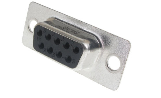
Some other facts of note are that serial ports (See Figure 1) can only communicate with one device at a time, which means that typically there is one device at each end of a serial cable and no more. Other serial communication protocols such as USB can have several devices connected to the same cabling (called a “bus”) and communicate co-operatively and at much higher speeds than the RS-232 serial communication protocol.
If your microcontroller is communicating serially with another device, both the microcontroller and the other device can only see what the other is sending. Therefore, it’s important to be certain that the programs running the communication on each side is using the same protocol and baud rate.
This is by far one of the best descriptions of TTL and serial communications in general. Thank you very much.
Calvin
Sacramento, CA
To the points, both practically detailed and big pictured; Looking forward to learning more.
How does uart cable looks like ? Does uart and ttl cable look the same ? Do you have pictures ?
Nice. Thank you.