
Adding a “fudge factor” is actually a thing in engineering, but there’s a more formal-sounding name for it: de-rating. Both refer to the process of providing more robustness than is called for. There are many reasons for doing this. Sometimes new components are on the low side of average. For instance, electronics components are rated based on performance curves at various temperatures. More robust semiconductor dies that demonstrate adherence to performance curves at higher temperatures are sold as components rated at industrial temperatures. Everything has physical limits, and for electrical engineers who work on products that must perform in harsh environments, physical limitations are factored in as part of the electronics design process. Harsh environments include outer space, automotive engines, drill bit heads with integrated sensors, and inside the human body, for example.
Component de-rating can be a rigorous process with tedious calculations. When sending a satellite into space, you would do more than just “add 10% more” for a safety factor. Component de-rating is part of a rigorous design process that ensures that components will not withstand more stress than they are designed for. Robust components are less likely to fail, with the added benefit of reducing the likelihood of getting damaged while under stress. (Damage under pressure can reduce the life of the product to where it operates as expected, but for a shorter-than-expected lifetime.) De-rating starts with an inspection of the datasheet for maximum rated values for both operating and storage states. Storage is also an essential consideration for many components from a materials standpoint. Integrated chip packages are made of plastic and can crack or craze based on temperature alone, regardless of whether the device is operating. Other examples are that capacitor dielectrics and batteries can freeze or burst with excessive heat.
De-rating may consider different types of stress besides electrical stress (e.g., overvoltage, current surges, brown power, etc.), and they are thermal stress, mechanical stress, and chemical stress.
Thermal stress occurs when a component operates or is stored at temperatures that are hotter or colder than the device is rated for. Excessive cycling of temperatures from hot to cold and back can also damage a part.
Mechanical stress: An electronic component may also have mechanical ratings, since a component experiences mechanical stress through vibration, thermal expansion, or shock (rapid acceleration/deceleration). Board connectors and headers can be especially vulnerable to mechanical stress and even introduce noise into a signal from physical vibration.
Chemical stress can also be considered for de-rating budgets. The constant presence of water vapor is enough to cause components to form layers of oxide that reduce the integrity of a contact connection. Solvents and corrosive materials for electronics operating in a harsh environment can also be a chemical stressor that leads to failure. Some components are rated for such situations because they are coated in a thick layer of epoxy resin to protect an otherwise average component.
As an example, EPCOS/TDK’s guide of general technical information for film capacitors states that “the rated voltage VR is the DC voltage for which a capacitor is designed. It is defined as the maximum DC voltage that may be applied continuously to the capacitor terminals at any temperature between the lower category temperature Tmin and the rated temperature TR.” (Get the EPCOS/TDK Technical Guide for Film Capacitors PDF.)
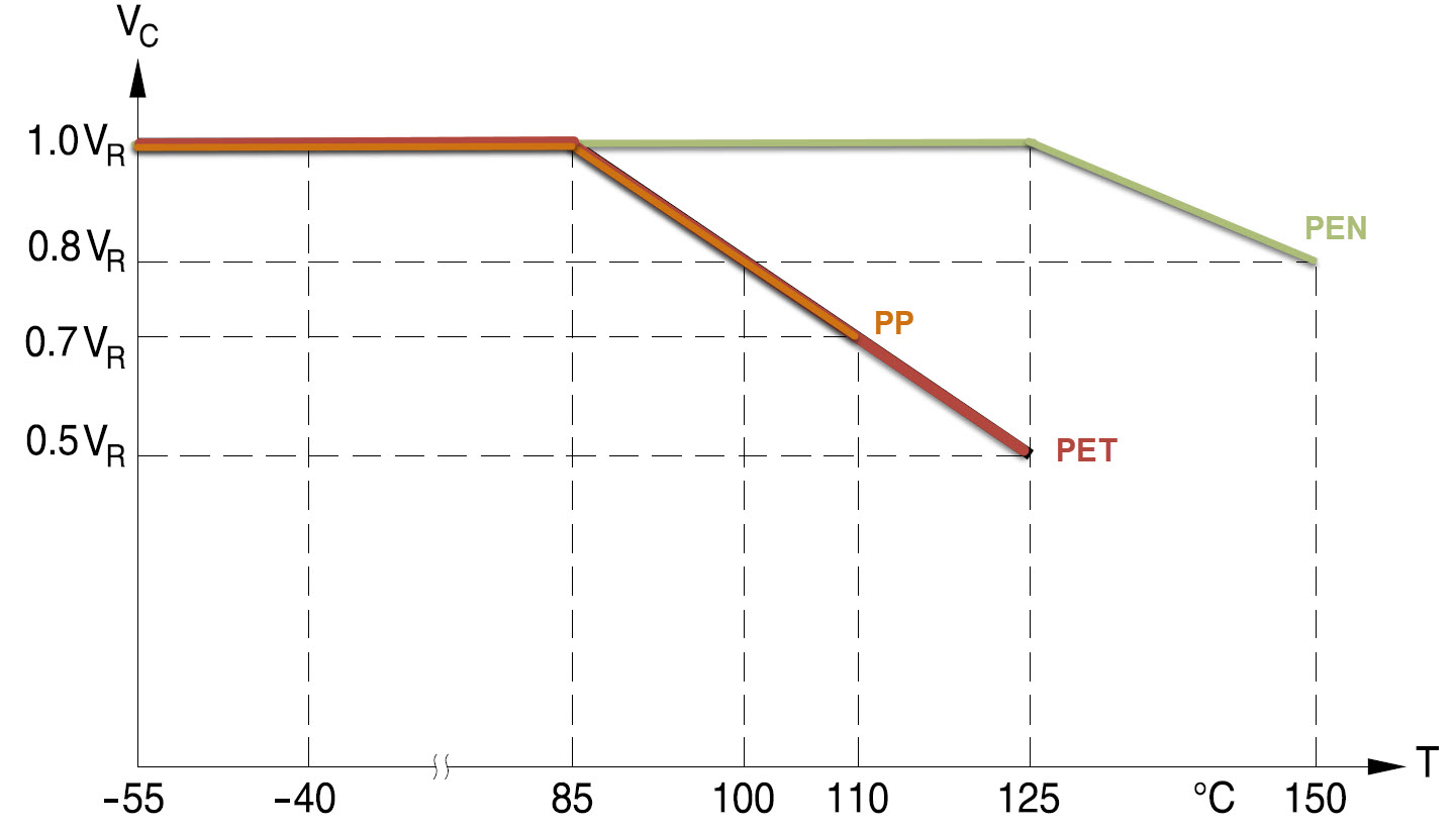
In Figure 1, the y-axis is labeled VC, which describes the maximum voltage that can be applied continuously to the capacitor. The rated voltage VR is the maximum continuous voltage at the given temperature (T). (I.e., VC=VR). Looking at the graph, if PEN is one type of capacitor, then when you try to operate PEN continuously above the rated maximum temperature (125°C), you can expect to operate it safely only at 80% of the rated voltage up to 150°C. Derating of PP and PET type capacitors is more pronounced at a 1.25% per °C derating factor beyond the 85°C rated temperature. TMAX is where the graph stops (125°C for PET and 150°C for PEN).
Yes, you can safely operate a capacitor above it’s rated temperature, but at a reduced voltage, and not beyond its maximum temperature rating.
There are plenty of resources for de-rating online, especially on government defense sites. The Naval Sea Systems Command, in a PDF from The Applied R&M Manual for Defence Systems (Part C) that covers a broad discussion of derating components (not just electronics), and a derating standard for electronics components sold online by the Society of Automotive Engineers (SAE) that the SAE states supersedes “the derating limits contained in Defense Standardization Program Office (DSPO) Standardization Directive SD-18, Naval Standard TE000-AB-GTP-010, and Air Force ESD-TR-85-148.”[i]
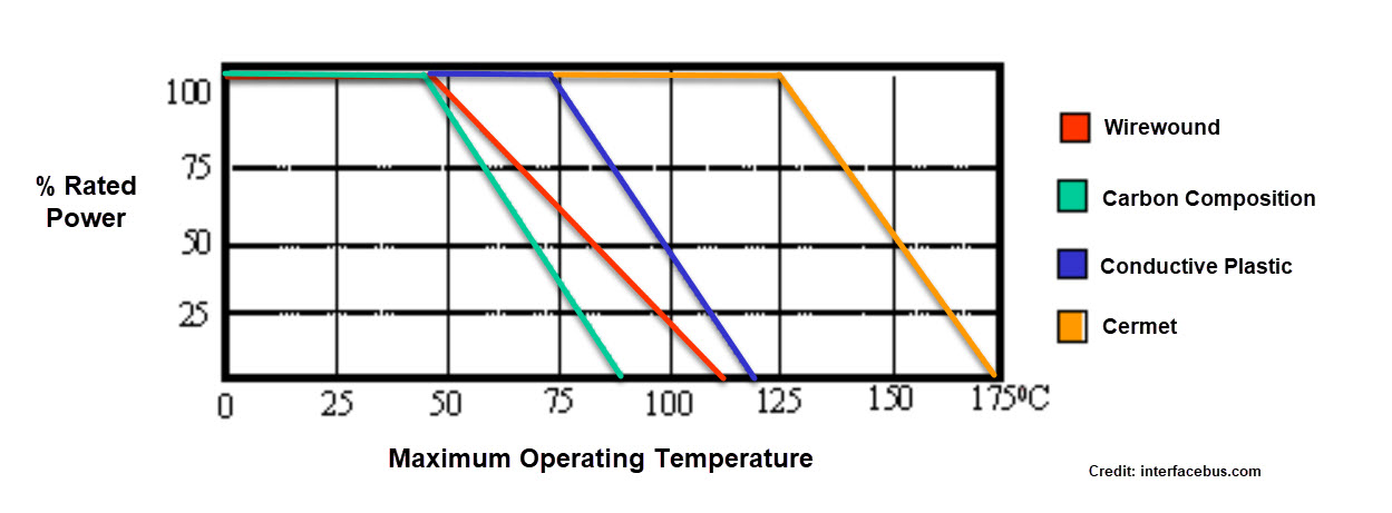
If you just need some general guidelines, a useful resource that includes derating of a broad range of electronic components is a site hosted by interfacebus.com as a Guideline for Derating Electronic Components which provides derating factors for wire, potentiometers, resistors, fuses, switches, inductors, and more. NASA also has a 338-page document that covers derating, the EEE-INST-002, which is available for download.
The Applied R&M Manual for Defence Systems states that “a significant number of equipment failures are due to incorrect selection and application of capacitors.”[i]
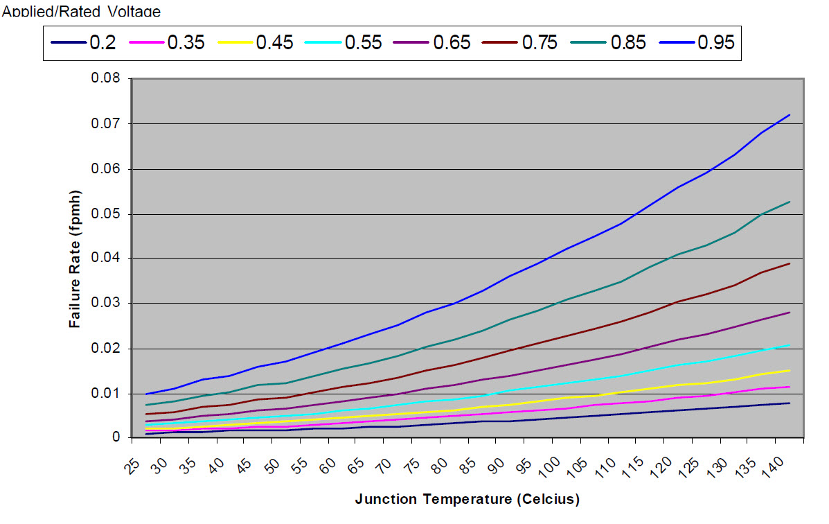
Figure 3: An example of a derating characteristic for a bipolar transistor. (Source: Applied R&M Manual for Defence Systems)
Derating is an intentional process for all kinds of components, not just electrical components. In electronics, derating can be considered for both active and passive. Derating reduces stress on electronic components that are operating under normal conditions by running them at less than their maximum power rating. Derating minimizes the chance of degrading components and prolongs component life.
_______________________________________
[i] The Applied R&M Manual for Defence Systems, http://sars.org.uk/BOK/Applied%20R&M%20Manual%20for%20Defence%20Systems%20%28GR-77%29/p3c07.pdf, accessed 4/29/2018.
The Applied R&M Manual for Defence Systems states that “a significant number of equipment failures are due to incorrect selection and application of capacitors.”[ii]
[i] Derating of Electronic Components GEIASTD0008, pub Aug 2011, https://www.sae.org/standards/content/geiastd0008/, accessed 4/29/2018.
[ii] The Applied R&M Manual for Defence Systems, http://sars.org.uk/BOK/Applied%20R&M%20Manual%20for%20Defence%20Systems%20%28GR-77%29/p3c07.pdf, accessed 4/29/2018.
Leave a Reply