
Using a low power microcontroller and making it “sleep” as much as possible is a common power reduction technique as they can be woken by either an internal or external clock, or by an internal or external event. Taking the PIC 8 bit XLP devices as an example (the so called nanoWatt devices), they have a sleep current of typically 50nA at 3V and 20nA at 1.8V. This requires everything to be shut down and care with the setup and state of any I/O pins. The watchdog timer, brown-out reset, fixed voltage reference, and oscillators need all to be disabled and all peripherals inactive.
Using the watchdog timer will typically increase the current to around 300nA at 1.8V and 500nA at 3V. This is pretty good but you also need to consider the energy consumed once awake. Clock startup time is quoted as typically 5μs for HFINTOSC which is the 500kHz clock from which the high frequency clocks are derived. This mainly matters when you are considering the response to an external event rather than as a power consumption issue – if the clock isn’t running it probably isn’t taking much power.
However, experimental results with a specific design required delving a little deeper into the nature of the oscillator startup as it is not qualified in the data sheet. There is a flag which allows you to check the internal oscillator is running although if you are actually running from the internal oscillator that is of little use because if it wasn’t running your software wouldn’t be able to check the flag. It is of more use when switching between two clock sources. There are two other flags which allow you to check if the high speed internal oscillator is within 2% and 0.5% accuracy but startup times for those accuracies are not given.
If you simply want to execute a few instructions (10 in my tests) and then sleep again with no clock checking that can be done in around 10μs. While this may seem a long time for 10 instructions with a 16MHz clock (4MIPS), you have to bear in mind that the clock is only running at around a third of full speed at startup. The test program should have taken 10 instruction cycles so averaged around 1MIP. This in itself isn’t a problem assuming you have nothing time critical. The typical startup current for the 10 instructions (including the SLEEP instruction) is shown below where the Y scale is voltage across 100� so 50mV = 500μA.
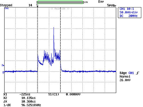
So, the current is approximately 500μA for 10.36μs. If the microcontroller was woken every 16ms by the watchdog to execute those 10 instructions the average current (at 3V) would be roughly 500nA + 500μA * 10.36μs/16ms = 824nA. A good figure although you are likely to want to execute more than 10 instructions and may want to do it more often than every 16ms.
In the application where I needed to investigate the clock startup, I was experiencing erratic timings from a PWM after wakeup. If you simply want to run some code and have nothing that is time critical then you can simply ignore all the clock flags and run your code when waking up and then go back to sleep as quickly as possible. However, if you have something that is time critical such as a UART or something such as a PWM which, while not critical, cannot be driven with a wandering clock, then you need to be aware of what happens to the clock on startup and the significant impact it can have on your power consumption.
If you wait for the clock to be 2% accurate, the current [voltage across 100 ohms] looks like this:
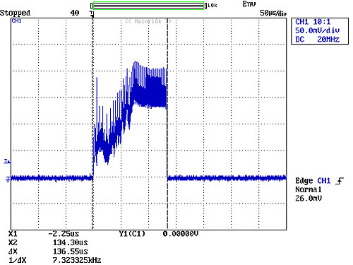
So, you are now waiting for roughly an extra 125μs for clock to stabilize and average current is 10.9μA compared to 0.8μA in the earlier example – more than 10 times the current. While you may argue that you could simply run a PWM while the clock is still ramping up, what is not obvious in that waveform is the wandering nature of the clock frequency during startup. It speeds up and slows down on its way to full operating frequency. This can be partly seen in the trace above where the current drops after around 20μs then climbs again. This effect has been confirmed by software tests without the current monitor where a nominal 250ns pulse width was 644ns early in the startup but then increased to 1.1μs before then reducing again on its way to the target 250ns.
The current spikes in the waveform are actually from the 500kHz internal clock from which the high speed clocks are derived, using a PLL. This is separate to the additional post-scaler PLL that can be used to increase the frequency from 16MHz to 32MHz.
Waiting for the oscillator to stabilize to 0.5% accuracy results in the following:
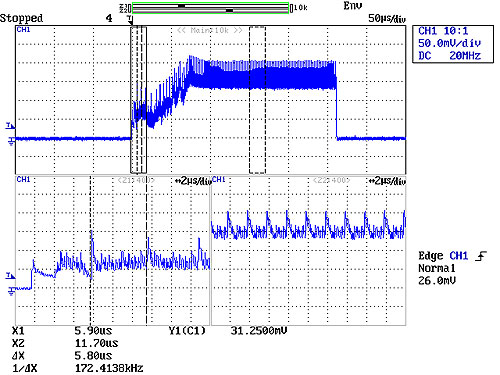
Here the timing of the early clock pulses and the later ones have been zoomed. In the early stages of startup the 500kHz clock is 172kHz. After the initial ramp-up the 2μs period of the 500kHz clock can be seen. The average current would be 22.5μA compared to 10.9μA for the previous example.
From a power consumption point of view the power would be expected to be roughly proportional to the clock speed so running slower would take longer to execute but the power consumption would be proportionally lower so the energy required to execute those 10 instructions would be roughly constant regardless of clock speed. This is not actually the case – the processor is more efficient at higher clock speeds. At 16MHz using the internal oscillator it takes 1.4mA at 3V and at 8MHz it takes 0.9mA (data sheet figures). So, the faster clock speed is more efficient. This is not true when the 4xPLL is used to derive a 32MHz clock. With the 4xPLL, current is more than double for double the speed.
In summary, the impact of clock startup times can be significant if you need to wait for accurate clocks. If you have non time-critical software to run as well as the time-critical software then you can minimize the power consumption by organizing your software so the non time-critical software runs first and then check the clock accuracy flags before continuing. If none of your software is time critical then you can simply ignore the clocks accuracy flags. Otherwise care is needed in organizing the software and choosing the clocks in order to minimize power consumption. While these tests were carried out on PIC microcontrollers, it is likely that the detailed operation of other makes of microcontroller would require careful investigation to minimize power consumption.
Leave a Reply