Giant magnetoresistance sensors are strong candidates for the high-accuracy wheel-speed sensing necessary in autonomous vehicle systems.
Christine Graham | Allegro MicroSystems
The purpose of a braking system has evolved from simplistic stopping to critical functions in vehicle safety through highly accurate feedback to traction control (TCS) and advanced driver assistance systems (ADAS). These advances have been made possible in part due to the technological developments in magnetic wheel-speed sensing.
Integrated circuits for magnetic sensing have evolved from simple 100-transistor designs to those containing hundreds of thousands of transistors. The Hall effect is a common transducer technology used in sensor designs. The Hall transducer interfaces with processing circuitry to produce a switching square wave representing either speed or speed and direction for the braking control unit’s processing algorithms. Hall effect-based wheel-speed sensors have helped move braking system technologies from standard anti-lock braking (ABS) capabilities to traction control (i.e. anti-slippage) and full stability control (vehicle maneuverability).
The Hall effect, discovered in 1879 by Sir Edwin Hall, refers to the voltage produced when an electrical current flows through a conductive plate while it sits in a magnetic field. The resulting voltage is perpendicular to and proportional to the current and magnetic field applied. This Hall voltage is small in amplitude and susceptible to temperature variations. So it takes special signal processing to effectively integrate it into a sensor IC.
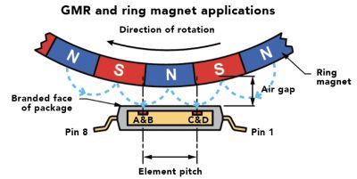
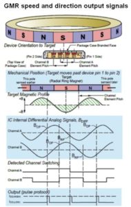
Wheel speed sensors monolithically integrate Hall transducers on a single silicon substrate with signal conditioning circuitry. These plus compensating algorithms provide a reliable output square wave to the control unit. The Hall IC is either used in combination with a back-biasing magnet to sense a ferromagnetic target (such as an iron-based gear) or the IC directly senses a magnetic encoder ring (a.k.a. ring magnet), also known respectively as back biased (gear) or front biased (ring magnet).
Hall-effect wheel speed sensors provide edge accuracy down to tenths of a degree with the air gap between the sensor and target typically in the 1 to 2-mm range. This amount of accuracy has been adequate for most of today’s braking systems, but not for driver assistance systems far beyond traction control that are quickly evolving.
From park-assist to collision avoidance, the wheel speed sensors provide valuable data back to the driver assistance system, allowing it to decide the best vehicle maneuver before the driver even sees the oncoming hazard. The growing desire to automate the driving process is defining the future of wheel speed sensing technology.
Signal conditioning

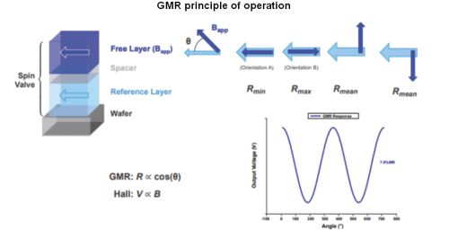
Although the Hall effect meets current needs, driver assistance systems require higher accuracy at similar, or in some cases larger, air gap distances between the sensor and the sensed target. Giant magnetoresistance (GMR) is a strong candidate to meet these enhanced requirements. Front-biased magnetic encoder rings are the most common target type in today’s light vehicle applications and the most common implementation for GMR. The GMR replaces the Hall effect as the sensing transducer. In principle, GMR and Hall are both magnetic sensors, but the two differ in fundamental operation and capability.
Magnetoresistance is said to have been observed by Lord Kelvin in 1857, but GMR specifically was discovered over a century after the Hall effect in 1988 by Albert Fert and Peter Grünberg, earning them a Nobel Prize in 2007. The fundamental principle of the GMR effect is based on electron spins. In a magnetoresistor, electron scattering rates rise or fall as a function of the interaction of the spin state of the electrons and the magnetic orientation of the medium where the electrons are traveling. Electron scattering increases the mean free path of the electron flow, effectively altering the resistance of the medium. Simply put, the GMR transducer’s resistance changes in the presence of a magnetic field.
Earlier generations of MR technology limited sensing angle, linear range, and sensitivity. These limitations have been overcome in Allegro’s state-of-the-art patented GMR technology, providing greater range, and higher sensitivity. The sensing orientation allows the GMR sensor to be a drop-in replacement for Hall effect sensors.
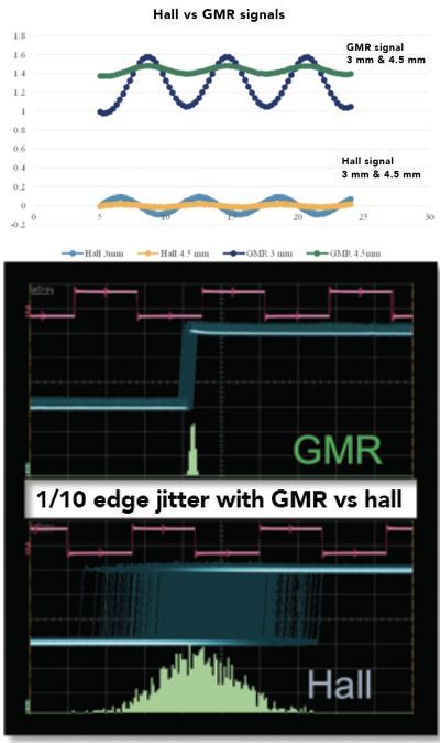
Historically, the GMR was oriented 90° out of phase from the Hall effect sensor making it difficult to swap the technologies. Another issue seen in earlier MR designs is that of discontinuities in the signal at close air gaps. The signal perturbation directly correlates to higher edge jitter, reducing the wheel speed sensor’s output accuracy. Nearly a decade has been spent overcoming the signal discontinuities in wheel speed sensors now available, such as Allegro’s A19250 and A19350 GMR wheel speed sensors. In addition to low jitter, these sensors offer large operating air gaps which extend far beyond the capability of Hall transducers.
Like Hall effect technology, GMR is monolithically integrated onto a single silicon substrate with signal conditioning circuitry. However, the resulting GMR signal is magnitudes higher than a Hall signal with much greater signal-to-noise and one-tenth the jitter. These qualities let GMR sensors sense objects at much bigger air gaps.
The magnetic design range for Hall-based sensors specifies a minimum operating field level of 20 gauss (2 mT) differential peak-to-peak. In contrast, GMR-based sensors have a minimum operating field level of 5 gauss (0.5 mT) or lower differential peak-to-peak. Comparing the accuracy, the Hall capability is tenths of a degree edge accuracy at 1.0 to 2.0 mm typical air gap, while the capability of GMR is hundredths of a degree of edge accuracy at typical air gaps of 3.0 mm or beyond.
GMR does require more stringent design-in conditions. One difference between the technologies is the capability of Hall to handle larger magnetic fields. This is a function of the sensitivity and a key part of the design process. GMR has a defined linear range with ideal peak-to-peak magnetic signal amplitude in the 100-gauss range.
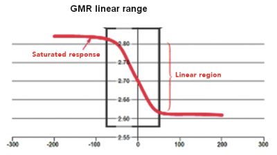
GMR devices, like those employing the Hall effect, will operate outside of the magnetic design range without permanent damage. However, depending on the signal processing algorithms, the performance may degrade. This degradation can arise with either technology, but GMR high sensitivity levels come at the cost of degraded performance at a higher magnetic field level. The magnetic field strength and temperatures at which GMR transducers can experience permanent damage are much higher than those expected in wheel speed applications, so they aren’t much of a concern. The primary design consideration is to optimize the magnetic circuit for superior performance with GMR technology.
 All in all, state-of-the-art GMR technology has played an important role in realizing today’s highly accurate advanced braking systems. The vehicle response is so smooth the driver hardly notices it. GMR technology will play a similar role in semi and fully autonomous vehicles.
References
Brian Cadugan, Allegro ICs Based on Giant Magnetoresistance (GMR)