All microcontrollers (MCUs) require some sort of mechanism to program them, even if they only get programmed once. Typically, program code is written on a host computer, then it is compiled or translated, and object (machine-readable) code is downloaded to the MCU (“the target”) from the PC (“the host”) using a cable (usually USB or RS232) that (with some software) is often referred to as a “programmer.” Once programmed, the MCU functions as coded.
One very popular MCU development board manufacturer is Arduino, based in Italy. Many Arduino boards are populated with AVR microcontrollers, which also require programmers for saving programs created on the host computer into the target MCU’s memory, such as the AVR microcontroller. External programmers are often used for AVR microcontrollers and can be costly.
Most target MCUs have to be programmed several times during project development, so it’s not feasible to remove the MCU from the circuitry to program it. Many MCUs, including AVR processors, can be programmed using an In-system Programmer (ISP) so they don’t have to be removed from the circuit board. [i]
By default, Arduino boards have MCU-resident code called a bootloader. Bootloaders are the first programs to inhabit an MCU when you power them up. Bootloaders instruct the MCU what to load or do next. Arduino makes communication from the PC host to the board-resident MCU (target) easy to use with an Integrated Development Environment (IDE). An IDE is host-resident and includes tools that developers can use to program, compile, and debug the target MCU.
The bootloader also aids communication between the Arduino IDE and Arduino Board using USB. The bootloader is responsible for writing code on the chip as it arrives from the Arduino IDE.
Arduino development boards have an overall design that makes them easy to use, including free software tools. Arduino controller boards are very popular for starting in embedded programming and are often used in educational settings. A simple USB connection between an Arduino development board (the target) and a host computer makes Arduinos suitable for developing embedded projects without having to understand how to get program code into an MCU and running the code from there. (Arduino calls a program, or code, a “sketch.”) Arduino boards are most suitable for small-scale projects.
However, if the goal is to design an economical product, then creating high volume, production-quality boards using an AVR microcontroller on a custom-designed printed circuit board is cheaper than buying hundreds or thousands of Arduino boards populated with the same AVR MCU. Nevertheless, many have used Arduino (and similar) low-cost development boards as an installed, final product if it’s cheaper to avoid creating and stuffing a small run of PCBs.
Arduino boards have a small amount of general purpose I/O and can be used for many different purposes. For instance, Arduino boards can act as a programmer tool for other AVR microcontrollers using an Arduino ISP and is one of the easiest and cheapest methods for programming AVR MCUs. The Arduino in-system programmer is a built-in function offered in the free Arduino IDE. The ISP allows you to program Arduino boards and other AVR microcontrollers using another Arduino board that is dedicated for the purpose.[ii]
Programming a newly-developed Arduino board using a fully functional Arduino board (as a programmer-Arduino) has a few stipulations, however. First, the “programmer-Arduino” (the Arduino that you have configured as a programmer) must be configured as an ISP. The sketch (code) is by default available in example code within the File menu of the Arduino IDE. [iii] The Arduino ISP sketch passes the required instructions to the Programmer-Arduino to set it up in programming mode.
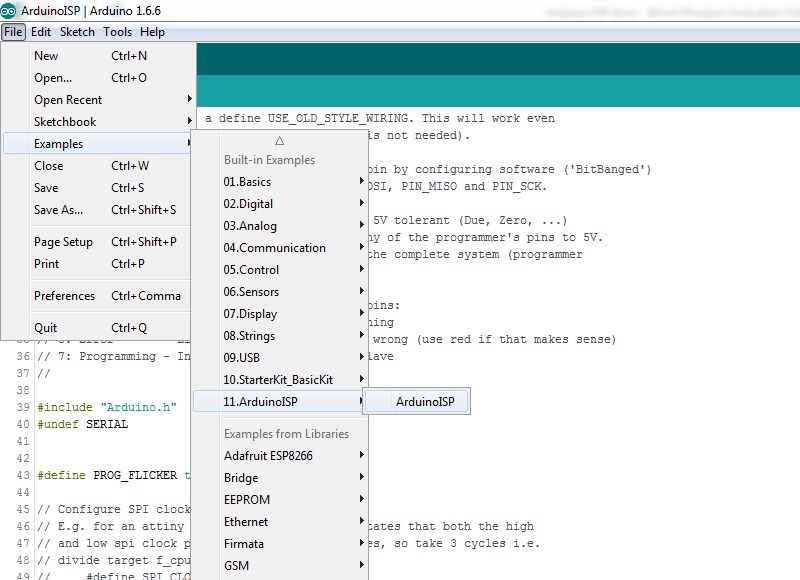
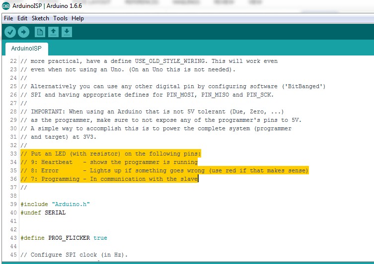
The status of Programmer-Arduino can be monitored with LEDs connected as shown. The Arduino ISP sketch is preprogrammed for this functionality.
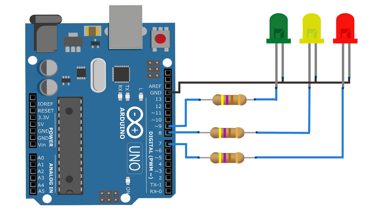
Pin 7 = Programming (Turns on during programming)
Pin 8 = Error (Turns on in case of programming error)
Pin 9 = Heartbeat (Stays on once the programmer is powered on)
After configuring the Programmer-Arduino, the connection between the Programmer-Arduino and the Arduino target gets established. The pin configuration needs to be done exactly as mentioned in the Arduino ISP sketch.
The Arduino ISP communicates using the Serial Peripheral Interface (SPI) protocol for programming AVR microcontrollers. SPI communication uses 4 logic signals: MOSI, MISO, SCLK, and SS. Other than I2C, SPI is one of the more commonly used modes of communication for MCUs. SPI follows a master-slave architecture, which means a master device can communicate with multiple slave devices using the same data pins, and the target slave device is selected using the slave select line. If there are memory cards, slave select is used for selecting a particular chip among multiple chips. However, when you use the Arduino as a programming tool, the slave select signal is used only to reset the microcontroller. Resetting a microcontroller puts in a state of accepting commands from the programmer Arduino. [iv]
On the Programmer-Arduino, pins 10, 11, 12 and 13 are used as data pins. The configurations are as follows:
Pin 10 = RESET
Pin 11 = MOSI
Pin 12 = MISO
Pin 13 = SCK
The 5v and ground pins can be connected from the Programmer Arduino. It is essential to connect reference ground of both Arduinos to avoid experiencing glitches as well as maintaining safety.
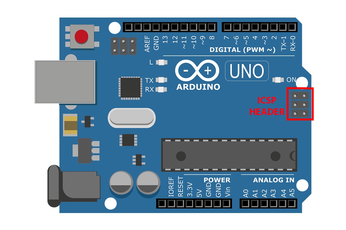
In-circuit serial programming (ICSP) is the ability of a microcontroller to be programmed without disconnecting from the circuitry. The ICSP header is physically available on the Arduino Board in the form of 6 pins. Connect pins 11, 12, and 13 of the target Arduino with pins 11, 12, and 13 of your programmer Arduino. Note that Pin 10 of your programmer Arduino should connect to the Reset Pin of your target Arduino. Alternatively, the ICSP header pins can be used for SPI communication. (See Figure 4).
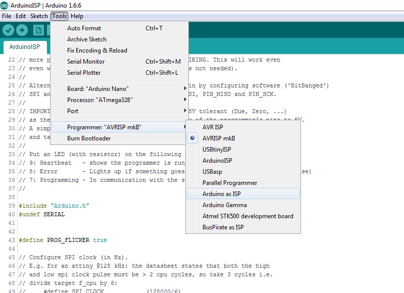
After wiring everything in the above, you need to define that you are using the Programmer mode from your host PC. Go to Tools in the Menu and select “Arduino as ISP” in “Programmer” options. (See Figure 5).
Next, load the bootloader into the memory of your target Arduino, and then define your “fuses.” In Arduino-land, fuses are a set of instructions for defining multiple functions in a microcontroller. For example, chip frequency and clocking source are defined in fuses. Microcontrollers are sensitive to operating voltage, and if the voltage level drops below a defined level, the microcontroller may malfunction. The minimum operating voltage is also defined inside fuses. [v]
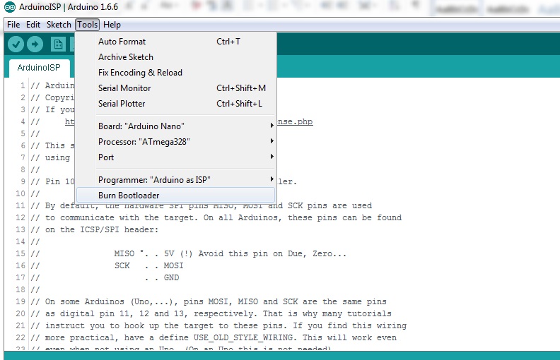
The above steps are essential if a Programmer-Arduino is to be configured so that it is compatible with the Arduino IDE for direct sketch uploading. The “burn bootloader” option is in the tools menu, too, and burns the bootloader to your target Arduino (see Figure 6).
There are various advantages if the microcontroller or Arduino board can communicate with the Arduino IDE program, such as being able to examine results at runtime using a Serial Monitor of the Arduino IDE. (The Serial Monitor opens in a separate window, acting as an independent terminal that receives and sends serial data.)
If the bootloader is not loaded in the microcontroller, it won’t be able to use Arduino’s features and will not be able to communicate with the Arduino IDE.vi The bootloader consumes a part of memory. In some cases, using the Arduino IDE is not required, and so the bootloader does not need to be programmed. If the bootloader is not programmed, more memory can be freed for the main program sketch. For example, in the Arduino UNO, the overall memory size is 32 KB, and 0.5KB of memory is allocated for the bootloader. vii If the bootloader is not installed, the overall memory available for the main program sketch is greater.
Arduinos are good for learning and experimenting with new ideas. Since the Arduino is open source, including hardware design schematics and Gerber files, anyone can copy the Arduino, modify it, and use it in a commercial context if they want to. Arduinos aren’t exactly a cash cow, but rather a labor of love, redefining how embedded hardware is passed.
i https://ieeexplore.ieee.org/document/8005274
ii https://www.arduino.cc/en/Guide/ArduinoISP
iii https://www.arduino.cc/en/Tutorial/ArduinoISP
iv https://www.arduino.cc/en/Reference/SPI
v https://www.arduino.cc/en/Hacking/MiniBootloader
vi https://www.arduino.cc/en/Tutorial/ArduinoISP
vii https://en.wikipedia.org/wiki/Arduino_Uno#Technical_specifications

just wonder if there is a way to program a chain of arduino’s…
Sir thank you soo much for your brilliant explanation.Awesome!!!!!!!!!.
Very good explanation. Thank you! Keep writing more such articles.
a good starters pack there
Could I use the ICSP port as SPI (10, 11, 12 y 13) pins?