Depending on the intended tasks and the associated range of motion, robots can have varying axes and various axis configurations called robot kinesiology. This FAQ will consider robot axes, kinesiology, drive safety functions, and power architectures. Subsequent FAQs will focus on “Robot software environments and motion control architectures,” “Sentient robots and artificial intelligence,” and “International performance and safety standards for robots.”
A robot axis of motion is often called a degree of freedom (DoF). For example, a robot that can operate in the x, y, and z planes has three DoF. If that same robot were designed with the ability to tilt or turn, it would have additional DoF. Robots with higher DoFs have access to a greater amount of space and can perform more complex tasks. Examples of the increasing capabilities resulting from higher DoFs include:
- 1-axis robot is capable of linear motion in a single dimension.
- 2-axis robot is usually composed of two linear guides that enable two-dimensional motion, such as an x, y, or y, z configuration.
- 3-axis robot is a basic 2-axis design with an additional linear axis guide, or a cylindrical guide, that enables x, y, z motion.
- 4-axis robot adds the ability to rotate the object that it is holding.
- 5-axis robot adds the ability for two-dimensional rotation of the object it is holding.
- 6-axis robot can mimic the motions of a human arm with three linear DoF and three rotational DoF.
- 7-axis robot is a six-axis design placed on a rail or stage that enables it to move linearly from one location to another.
Vertical articulated industrial robots are an example of a robot that mimics a human arm’s structure and motion capabilities. These robots have a serial link mechanical structure and are usually comprised of six joints that enable six DoF. The lengths of the various segments can be varied to suit the needs of specific applications.
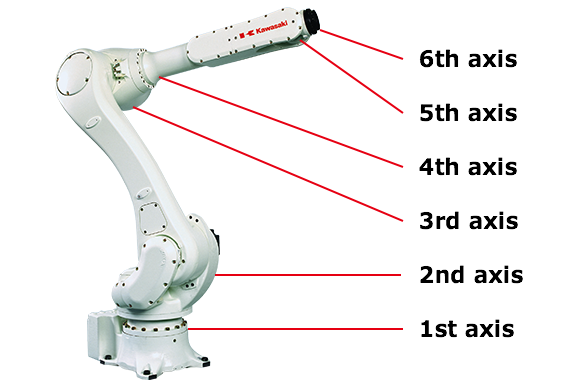
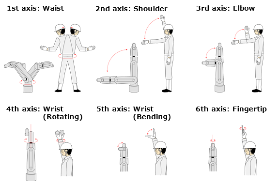
Axes 1, 2, and 3 correspond to the waist and arm, axes 4, 5, and 6 correspond to the motion from the wrist to the fingertips. The first three axes move the “wrist” to a specific position, and the other three axes provide the “wrist” with complete motion.
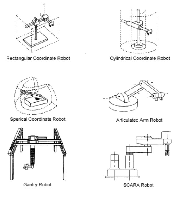
Different robot physical structures have different advantages depending on the application. The typical types of industrial robots are:
- Articulated robots such as those described above have a rotary axis and have 3 to 10 or more DoF.
- Cartesian robots (sometimes called rectilinear or gantry robots) have three linear axes, x, y, z. two-dimensional cartesian robots often have three axes, two for location x, y, and one for rotation and orientation of the tool. To be able to move freely in a three-dimensional space, cartesian robots require 6 DoF.
- Cylindrical robots operate in a cylindrical-shaped work environment and have at least one rotary axis at the base and one or more prismatic (linear) axes.
- Delta robots (also called parallel link robots) consist of parallel links connected to a common base. Delta robots are used in pick-and-place systems.
- Polar robots (also called spherical robots) connect the manipulator to the base with a twisting axis and a combination of two rotary axes and one linear axis. These robots operate in a polar coordinate space and have a spherical work envelope. They are found in welding, die casting, and injection or extrusion machines.
- SCARA (selective compliance assembly robot arm) are often used in assembly operations. They vary on the cylindrical design and have two parallel axes that provide movement in one plane.
Robot specification parameters
In addition to parameters discussed above, carrying capacity, speed, acceleration, kinematics, accuracy, and repeatability are important specification for robots:
Carrying capacity is simply how much weight the robot can handle.
Speed is more complex; it measures how fast the robot can position the manipulator. It can be specified in terms of the linear or angular speed of each axis, or as a compound parameter such as the speed of the manipulator when all axes are in motion.
Acceleration can also be a complex specification. A robot can often not reach the maximum specified speed over short distances or when moving in a complex path requiring frequent changes of direction.
Kinematics describes the physical arrangement of the various robot elements, which define the robot’s possible motions. Classes of robot kinematics were described above and include cartesian, parallel, SCARA, cylindrical, etc.
Accuracy measures how closely a commanded position is reached. Accuracy can vary with speed and position within the work envelope and the amount of weight being moved.
Repeatability measures how accurately a robot can achieve repetition of the same task.
Measurement of accuracy and repeatability can be challenging. ISO 9283 requires that they should be measured at maximum speed and maximum payload. Using the maximum values results in “worst-case” measurements. A typical robot will be significantly more accurate and have higher repeatability levels at slower speeds and lighter loads. Repeatability can also be subject to the end effector’s capability, such as a gripper, particularly if the design of the end effector is not optimized for the specific task being performed.
Drive safety functions
Industrial robots are subject to a variety of performance and safety standards. IEC 61800-5-2 is a drive-specific standard that defines various safety functions. Two of the most basic are:
- Safe torque-off (STO) is a stopping function that prevents torque-producing power from being provided to the motor. For example, industrial robot workspaces are often protected by an interlocked door or a proximity sensor. STO is designed to initiate an emergency stop if a person enters the protected space.
- Safe brake control (SBC) safely controls an external holding brake. It is always activated in conjunction with STO. SBC is typically used when the drive is switched off, and there’s a load affecting the motor.
STO is similar to an “inhibit” function on a motor drive. The difference is in how STO is implemented. Analog drives implement inhibiting based on grounding or ungrounding certain pins on the drive controller; digital drives implement inhibiting through software controls. In either case, if a drive is inhibited, a loose connection or other malfunction may re-enable the drive. Even if the drive is re-enabled for a brief period, unsafe (and unwanted) motion could occur.
STO is a safety function and is always required to be successful and not subject to external malfunctions. STO is not implemented through software or grounding control; STO forces a physical disconnect between the drive power and the motor phase connections. Once STO is initiated, the motor can’t start until STO is shutoff and the controller reengages the drive function.
Additional robot control and safety functions:
STO and SBC are only two of the several IEC 61800-5-2 drive safety standards. Additional standards include:
- Safe Stop 1 (SS1). Initiates a controlled deceleration to stop the motion and then initiates the STO function. SS1 is intended to bring a system with high inertia to a standstill very quickly.
- Safe Stop 2 (SS2). Identical to SS1, when the motion is stopped, the SOS (not STO) function is initiated.
- Safe Operating Stop (SOS). Monitors the stopped position of the motor and that the motor position is within a specified range. Sometimes considered an alternative to STO, but with SOS, the motor does not need to stop exerting torque. With SOS, the drive maintains position control, holding the position with zero speed.
- Safe Brake Test (SBT). An automatic test of the brake to ensure it provides the required braking action.
- Safely Limited Speed (SLS). Ensures that the motor does not exceed one or more specified speed limits. If a speed limit is exceeded, STO or SS1 is initiated.
- Safe Speed Monitor (SSM). Produces signals when the motor speed falls below a specified level or when the motor fails to reach the specified speed.
- Safe Direction Indication (SDI). Activates SSI if the motor is moving in an incorrect direction.
- Safely Limited Position (SLP). Monitors the absolute position of the axis and prevents it from exceeded a defined limit.
Power architectures for robots
Industrial robots employ a variety of powering architectures. Stationary robots typically employ ac/dc power supplies which can be single-output or multiple-output units. It is common to find multiple dc/dc converters used to power individual loads from the controller, drive(s), and sensors to the dc motors. Larger robots can employ a distributed power architecture where a relatively high distribution voltage delivers power to each subsystem. The distribution voltage can vary from 24Vdc to 700Vdc, or higher, depending on the system’s size. The highest distribution voltages tend to be found in larger mobile robots required to carry heavy loads.
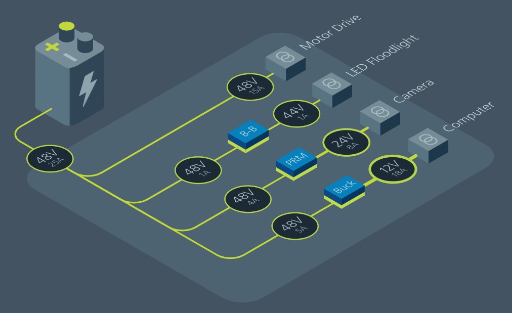
The figure above shows a mid-sized DPA that could be used in stationary or mobile robotics applications. If the system above were a fixed position industrial robot, the battery would be replaced with an ac/dc power supply that produces the distribution bus voltage.
The 48Vdc main power bus can directly power motors for various functions such as pumps and fans in automobiles or motive power in robots. The 48Vdc distribution voltage can be down-converted to voltages between 24Vdc and 44Vdc to drive various LED lighting, cameras, sensors such as LIDAR, and so on. And it can be converted down to 12Vdc to power an intermediate power distribution bus for various digital and analog functions with additional non-isolated dc/dc converters used to power the functions in the “computer” section.
The next FAQ in this series will consider “Robot software environments and motion control architectures.” “Sentient robots and artificial intelligence” will focus on the third FAQ, while the final article in this series will review “International performance and safety standards for robots.”
References:
A Guide on the Components and the Movement of Robot Arms, Kawasaki
An Engineer’s Guide to Industrial Robot Designs, Texas Instruments
Concepts of a Modular System Architecture for Distributed Robotic Systems, MDPI
How Many Axes Does Your Robot Need? ASME




Leave a Reply