by Oivind Loe, Chief Technology Officer, Sipsby.com, and Josh Norem, Staff Systems Design Engineer, Silicon Labs
Product returns for Internet of Things (IoT) devices can be challenging. On the one hand, connected the device should be locked down as much as possible when going out to the field. On the other hand, when a device fails in the field, you want the ability to open the device up to understand the root cause and remove the issue from future devices. Through new device security features, the best of both worlds can now be achieved.
As a device maker, you focus most of your attention on making the best product possible, making it attractive and valuable to customers, selecting the right materials, ensuring reliable manufacturing, and making sure the hardware and software are of high quality. You also take care of security and make sure the software can be updated in the field, so you can fix any issues that might come up. You might think that your job is now done, though, in fact, it has just started.
As more and more people use your devices, eventually issues are going to arise, and product success can often depend greatly on how you address these issues. Dealing with it poorly can result in angry customers, bad reviews, and eventually, a failed product. Dealing with it properly can make customers feel cared for, can sort out any issues with your product, and result in years of friction-free selling at large volumes.
Let’s take a closer look at the returns process and how failure analysis can be simplified through proper observability into the product without compromising product security and intellectual property (IP) protection.
Understanding product returns
A device can be returned to the device maker for several reasons:
- The device was dead on arrival.
- The device stopped working after some time.
- The device exhibits wrong behavior.
When a product is returned, large customers or distributors will want to know the impact of the issue and how to resolve it.
- What percentage of products are affected?
- What is the failure rate (daily, weekly, or monthly)?
- What is their exposure?
- What is the root cause of the failure, and your plan to fix it? How can you be sure you have found it?
- What do manufacturers need to do on their end to contain the problem for their operations or customers?
- How can they be compensated for the issue?
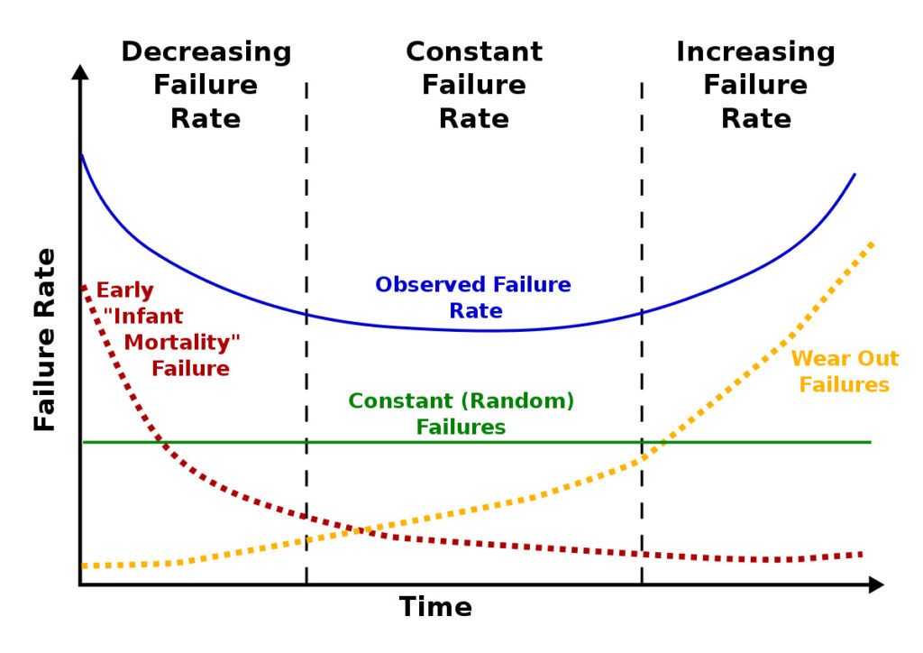
A device maker must be able to answer all these questions and more. The “bathtub curve” shown in Figure 1 is a simple model for the failure rate of a product through its lifecycle. Through proper handling of product returns, early issues are dealt with and improved on quickly, while random and wear-out failures are efficiently identified and communicated properly. Note that all the failure components can be improved through engineering and cost tradeoffs, and acceptable failure-rate differs between product categories.
A potential challenge with product returns is that not all failing devices are returned. Often a customer will expect a certain failure rate, and frequently, the device-maker is not notified until the failure rate becomes significant. For mature products, this is not an issue as failures are often not due to product issues, but for new and ramping products, this can be problematic.

The internal process
Once a product return is received, the device maker needs to determine what priority to put on the investigation. Some products are returned as a courtesy with no real pressure to get to a resolution quickly, while others might have significant demands behind them. It is up to the company to determine what level of investigation is necessary based on the circumstance.
One way to approach a product return is with Eight Disciplines Problem Solving, also known as 8D, a method developed by the Ford Motor Company to resolve problems. The 8D process includes these key steps:
- D0 – Problem summary including assessment of whether full 8D approach is necessary
- D1 – Team formation
- D2 – Problem definition
- D3 – Containment plan – controlling impact while root cause and final solution are being determined
- D4 – Root cause analysis – understanding the cause of the issue
- D5 – Corrective action plan
- D6 – Implement and validate corrective actions
- D7 – Prevent recurrence
- D8 – Sign off and commitment
Remedies to the problem come in two phases: Containment is the quick fix to minimize the impact of the issue and can be critical to resolving the problem in a timely manner. It can include but is not limited to halting firmware updates to devices, pulling affected inventory back from customers, implementing additional testing in production to catch the issue, and potentially stopping production altogether until the problem is solved. Being able to efficiently and accurately detect what products are affected can limit the negative impact of containment. In either case, communication with customers is key, as they are held responsible by their customers, and business relationships might be at stake.
The second phase of remedy is corrective action, applying the final fix to the problem once the root cause is understood. Finding the root cause of a problem can often be time- consuming and expensive, and there are cases where companies are unsuccessful in finding the root cause.
Note that an 8D may not be triggered based on product returns. It could also be triggered based on sudden increases in yield losses or other internally-discovered problems.
Failure analysis
Failure analysis or root cause analysis starts at the places that are a combination of easy to test and, based on experience, likely to reveal the root cause of many issues. This would often include visual inspection and running a product through production test to see if the device still passes or not. If not, that could indicate performance degradation in the field or intermittent product or test issues that were not caught during the first run-through.
Failure analysis goes on to other simple things, including looking for shorts, loose connections, and using probing tools to look for unexpected behavior. If a chip is suspected of having a problem, the chip could be replaced with a new chip or reprogrammed to see if the issue persists.
The most complex chip in a device is often the microcontroller or application processor. Unexpected behavior can be the result of several different causes, including but not limited to the following issues:
- Damage to the chip, either physical or electrical:
- Soldering at wrong temperatures could lead to delamination issues.
- Tensions in the PCB could crack the package and leads.
- Submersion in liquids could cause formation of metal whiskers leading to shorts.
- Improper handling could lead to ESD damage.
- Changed physical behavior due to wear-out:
- Sustained operation of IOs outside current/voltage limits over time could alter their characteristics.
- Significant transient voltage overshoot on pads could lead to damage.
- Excessive writes to the same flash regions could wear out specific flash bit-cells.
- Accelerated wear-out due to operation at high temperatures.
- Improper application behavior:
- Incorrect or improperly programmed flash image (weakly programmed).
- Incorrect application configuration or state in flash.
- Application exposed to unexpected environmental inputs; sensor readings out of range.
- Application bugs that were not discovered during testing.
- A problem with the chip itself:
- Chips have a failure rate measured in parts-per-million. Some failures are expected. Excessive failure rates could be the result of a manufacturing issue.
- Intermittent errors that only occur during certain conditions.
- Consistent failures, i.e., a function that does not work as advertised.
The above causes can result in a wide range of failure modes or behaviors. Issues (1)-(3) are the most common, but issues of type (4) do occur, and identified problems are reported as chip errata so developers can work around them. The remaining sections in this paper primarily focus on ensuring enough visibility into the device to deal with issues of type (3) – improper application behavior. This also applies to specific issues of type (2), such as characterizing wear-out related issues and uncovering any issues related to the chip itself (3).
Chip locking
To analyze an application to get to the root cause of an issue, it is often very useful to be able to see what is going on inside the chip: to read the flash contents of the chip to see if the program, configuration information and state variables are correctly written, and observe the program while it is running. There is, however, a challenge with this approach.
There are many reasons why a device maker does not want to allow anyone to dig into the chip and observe the application. The firmware on the device could be company intellectual property; the device could contain secret information such network keys, end-customer personal information or credentials, or the application could monitor quantities the user would be charged for, such as a water meter monitoring how much water the user is consuming.
For these reasons, a chip is usually locked down when it leaves production to prevent anyone from being able to access the inside of the chip, often including internal company personnel who want to perform failure analysis.
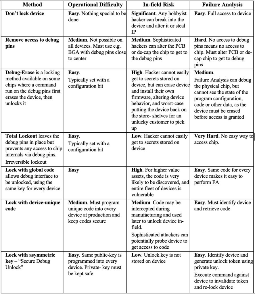
The mechanism to lock down a chip comes down to a clear tradeoff between security, ease of failure analysis, and operational complexity. Table 1 shows seven methods of chip locking and tradeoffs, including a new method to be implemented in future Silicon Labs wireless IoT devices; using asymmetric keys to enable a good combination of security and ability to do failure analysis, which is also known as “Secure Debug Unlock.”
Secure debug unlock provides several benefits. Other locking schemes force the device-maker to make a trade-off between operational complexity, security, and the ability to perform efficient failure analysis. This method makes the process easy by not requiring device-independent secrets to be programmed, has a high level of security, and allows full access to the chip during failure analysis, which is key to understanding device problems quickly.
Operational difficulty describes how difficult the method is to implement by engineering and manufacturing. In-field risk describes how easy it would be for a hacker to gain access to the device in the field. Failure analysis describes how easy it would be for device-maker staff to gain access to the device for failure analysis.

Secure Debug unlock
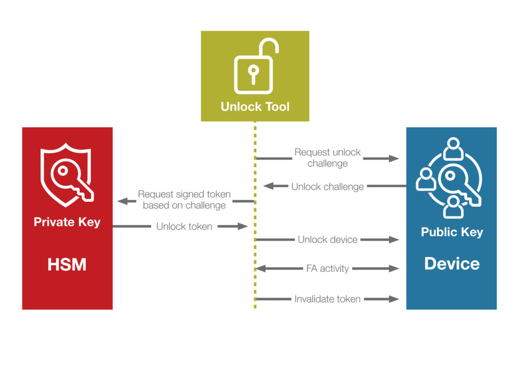
To enable the secure debug unlock capability for a series of devices, the device maker creates an asymmetric key-pair. The public key is programmed into every device at manufacturing, and the private key is kept safe and secure in a way deemed sufficient by the device maker. A hardware security module (HSM) might be a good option.
To unlock a locked device, e.g., for failure analysis, the device maker queries the device for a debug unlock challenge, as well as the unique device ID. Using the challenge, a debug unlock token is created and signed with the private part of the debug unlock key-pair by the device maker. This debug unlock token can now be used by failure analysis engineers to unlock the part to get the ability to debug and continue with their root cause analysis. An overview of this process is shown in Figure 2.
Once the failure analysis is completed, a command can be run on the device to invalidate the unlock token, preventing it from ever being used again.
With the secure debug unlock approach, the device maker holds the key to the device. If the device maker believes there is something wrong with the chip itself and sends it to failure analysis by the chip vendor, the device maker would have to generate an access token for the chip vendor to have access to the device. This puts control entirely in the hands of the device maker while still providing full flexibility for performing proper failure analysis.
Secure debug unlock can be a key enabler for secure, quick, and efficient failure analysis for situations when the error cannot be found through inspection, and the recommendation is to enable it wherever possible.

Conclusion
Dealing with field failures and other product issues are a natural part of building and selling embedded devices, and by dealing promptly and efficiently with issues that come up, a device maker can significantly improve the customer experience, product success, and business outcome. A solution must be chosen that provides full access to devices for failure analysis but without imposing a security risk or adding operational complexity. Locking a device using an asymmetric key, a technique that Silicon Labs calls “secure debug unlock” for wireless devices, maintains all the benefits of ensuring secure devices without adding complexity and risk.


Nice article from former collogues. Well done!