
Do you know the difference between single-ended and differential communication schemes? And when should you use them, which one you should use, and why?
Single-ended communications set ups are meant to be used only for short runs or to provide communication between devices on the same Printed Circuit Board (PCB). Single-ended communications will reference the signals with respect to ground. However, as the designer attempts to move devices farther apart from each other, the signals in a single-ended communications bus become susceptible to Electromagnetic Interference (EMI). EMI causes the ground and signal levels to shift out of spec such that bit levels cannot be distinguished. However, a differential communication (or signaling) system can significantly extend the distance between wired devices.
TTL logic levels
Electronic designs rely on the interconnectivity of the components to function. When components are in close proximity of each other, such as residing on a common PCB, the designer typically connects components directly with respect to a common digital ground plane on the board. The length of the board traces is short enough where signal loss from the resistance of the traces is negligible. Digital components can be easily connected as long as the components use the same logic levels.
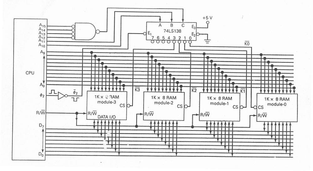
While there is little concern about line loss, direct connections of discrete logic components can take an excessive amount of board space to route all the necessary traces for complex devices. Consider the memory circuit shown in Figure 1. Using discrete memory integrated circuits (ICs), there are more than 120 connection points, just so we can access a measly 4 Kilobytes of memory. Imagine how many connection points there would be and the size of the PCB required to support 4 Megabytes or even 4 Gigabytes of memory using this scheme!
Modern memory
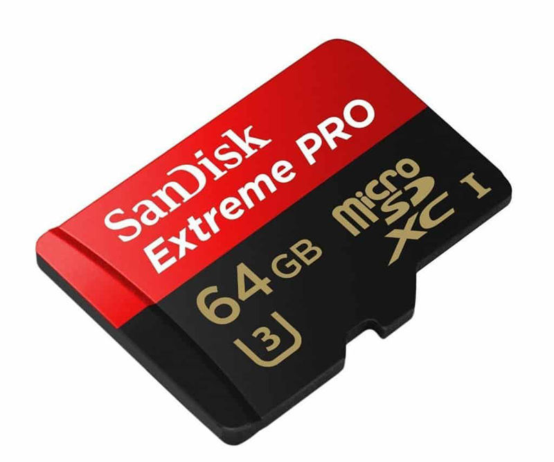
The ability to multiply the memory circuit above in Figure 1 comes from improved technology and manufacturing methods that move thousands of circuit connections on board a single chip. But with all the connections moved on board a single IC, how do you access the memory? Again, improvements in manufacturing and technology allow designers to interface with the device over a serial communication system. An SD Card is just one example of a serial memory device. While the latest cards can use a more advanced serial protocol, all SD Cards support the legacy SPI interface.
SPI interface
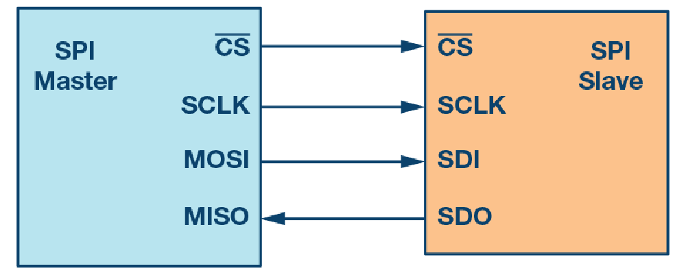
SPI stands for Serial Peripheral Interface. SPI (sometimes called “spy”) is a synchronous serial communication interface that uses only four wires for its connection to other devices. Data transfer takes place between a leader device like a microcontroller and a follower device like an SD card using a serial clock (SCLK), two data lines (MOSI and MISO), and a follower or Chip Select (SS).
The detail of the SPI protocol is beyond the scope of this article. However, the SPI example is mentioned because the communication signals are referenced from ground. Referencing communication signals from ground is also called “single-ended communication.” The characteristics of single-ended or logic level-based communications are that the connection needs to be short enough to prevent line loss and provide noise immunity from electromagnetic noise. This is why you see SD Cards used in cell phones, computers, and embedded controllers where they are designed on the same printed circuit board as the microcontroller or microprocessor they serve. The SPI interface does not lend itself to being connected remotely over a long distance from the microprocessor it supports.
I2C interface
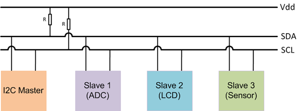
I2C (Inter-Integrated Circuit) is another common serial communication protocol. Like SPI, I2C is a synchronous serial communication interface. “Synchronous” means that it transfers data a bit at a time along the Serial Data Line (SDA). However, I2C requires only two wires for communication: The Serial Data Line (SDA) and the Serial Clock Line (SCL). While only two wires are needed for I2C compared to the four wires of SPI, I2C has a slightly lower transmission rate than SPI. One example of a memory chip that uses I2C is Microchip’s 24CW64. With only two pins for power and two pins for the I2C interface, this device can store 64 Kilobytes of data for a microprocessor. Just like the SPI example, the I2C EEPROM uses single ended, ground-to-Vcc digital logic levels for the I2C lines. Since memory chips are typically mounted near the microprocessor, concerns about line loss and noise immunity are low.
The I2C communications bus has expanded well beyond merely serial access to memory chips. Hundreds of peripheral devices exist that use I2C for easy integration to microcontrollers:
- Temperature Sensors
- Accelerometers
- Proximity Sensors
- GPIO Expanders
- Touch Sensors
- Color Sensors
- Distance Sensors
- Driver Control
- OLED Displays
- Other microcontrollers
- A-to-D Converter
- Light Sensors
Indirectly, interfacing to these devices is just like accessing the external memory locations of the microcontroller. If it makes sense for the peripheral to be mounted on the same PCB as the microcontroller, the designer still has little concern about line loss and electromagnetic noise immunity.
Electromagnetic interference: the problem with distance
What if you need a sensor in a location that’s remote from the microcontroller? Suppose you want to measure the temperature of something that exceeds the operating temperature of the microcontroller? You would need the thermocouple and sensor to be placed at a distance from the microcontroller. In another application, suppose you want to provide feedback to the user on a remote OLED display? Even passing messages between two microcontrollers in a distributed design would require communicating over a longer distance than the restraints of a single printed circuit board.
As the distances increase between I2C devices, the communication lines become more susceptible to EMI again. The effects of EMI may not appear obvious at first, but these problems are all around us in the physical environment. One basic electromagnetic principle is that current flowing through a conductor produces a magnetic field along the axis of the conductor. In turn, a conductor in a magnetic field will produce current in the conductor (Faraday’s Law). These two principles are how transformers, motors, and generators work.

But how do these principles affect the digital communication systems discussed above? As the designer starts to move peripheral devices off of the PCB of the microcontroller or attempts to talk between microcontrollers separated by larger distances, the communication lines become more susceptible to the inductive coupling of other devices in the environment. The communication lines are susceptible to having undesired current coupled into them by stray magnetic fields from transformers, motors, and other electro-mechanical devices. Relays and solenoids can be particularly troublesome using digital communications, due to the high in-rush of current when they engage and disengage. The current coupled into a single-ended digital communication system can drive the digital logic levels well above and below the accepted digital logic levels of the system. Influencing the logic levels to an unknown state between a digital high and low is just as troublesome for the data integrity of the digital communication system. While you should take care to try to prevent such interference, it cannot always be avoided.
Differential communication
At the cost of some more complex circuity and design considerations, the engineer can minimize the effects of electromagnetic interference. The most significant improvement can be the utilization of differential communication drivers to replace single-ended communication over long distances.
For differential I2C, our system goes from 2 wires to 4 wires. We still only have the data line (SDL) and clock line (SCL), but we will use two wires for each signal. As the name “differential” communication suggests, the digital value of a bit is the difference in the voltage level between the two lines for each signal. The precise voltage levels of each line become less important. Rather, it is which line is more positive than the other that determines whether a digital 1 or 0 is received. The differential transceivers on each end of the communication line will convert the differential signals to the digital voltage logic levels of the microcontroller(s).
When you choose wiring for differential communication, consider keeping both wires for a single data signal as close as possible to each other. A multiconductor cable or “twisted pair” wiring is excellent for maintaining that closeness. The reason you want to choose wiring like this is so that any influence from an external electromagnetic field will influence the voltage induced in both wires, and in the same way. If the electromagnetic field creates a one-volt drop in the differential communication lines, both conductors see the same voltage drop. Even though the absolute voltage level has changed, the difference between the two wires remains the same. In this way, the integrity of the data being transmitted over the differential line is maintained.
While you are trying to keep your single ended I2C solution within the size of a single circuit board, the differential solution can support distances of up to 10 meters at a 10K bits per second.
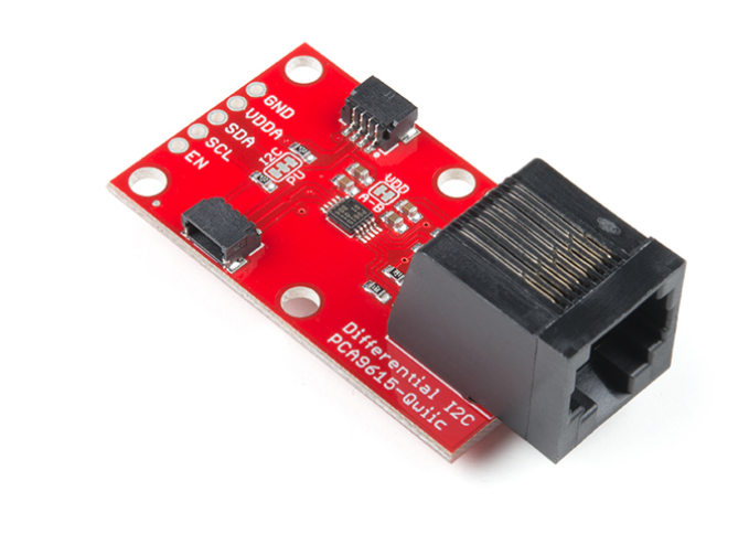
An example of an I2C differential driver is the PCA9615 by NXP Semiconductors uses this chip in a breakout board for prototyping and bench testing, too.
The PROs and CONs
Utilizing serial communication protocols can greatly reduce the number of connection points or pins as well as the size of your PCB design. If the design can be kept to a single PCB, single-ended communication between micro-controllers and peripherals is the easiest and most cost-effective solution. However, care must be taken if the peripherals need to be off-board or you need to communicate between microcontrollers over a significant distance. In these cases, spending the extra time and money to integrate a differential communication system is well worth the increased performance and reliability.

How absolutely retrogressive and insensitive that this article still refers to derogatory terms such as “SPI Master” and “SPI Slave”, “MOSI”, “MISO”, yet the IEEE and many manufacturers have already changed this terminology to “Controller” and “Peripheral”.
It is still very indicative of how backward this magazine is when referring to ancient, derogatory terms such as “Master and Slave” so cavalierly. Please update your literature to be more in line with current terminology.
Hello, Thomas,
Thank you for your feedback. I completely agree these are inappropriate terms.
However, Please note the publish date of this article (2019) and that the IEEE working group didn’t address this formally until this year (although it was discussed earlier). Also, please remember that given the volume of articles we publish, it is a challenging task to go back in time and adjust constantly evolving language in the thousands of articles we publish.
I have made the changes to the one instance of “master” and two to “slave”. These now read “leader’ and “follower” which are the two terms supported in the IEEE 802.1ASdr Editor’s Update here: https://www.ieee802.org/1/files/public/docs2021/dr-Rodrigues-editors-update-0921-v00.pdf. If you see better and more widely accepted replacements, please let me know.
While it is, as I say, a “challenging task” for a small staff, we encourage readers like you to help point these out – a sort of crowd-sourced fixit. Thanks, again.
Cheers,
Aimee
I think that this is a great article and the SPI Master, Slave, MOSI, MISO are just fine and should not be changed. This nomenclature is decades old and should not be changed to accommodate progressive political thinkers. We should not allow engineering terms an nomenclature to be politicized. BTW these terms are not derogatory terms they just are not. Please do not update your literature which would politicize aspects of engineering!