
The Covid-19 pandemic has forced many people to spend more time in front of a TV set. Here’s a look at what’s inside the cable box responsible for a large portion of home entertainment.
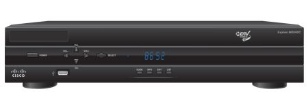
Examine the hook-up for many cable TV customers and you’ll likely find something like the Cisco Explorer 8642HDC DVR. This set-top box has been out for several years, long enough for numerous examples of it to show up on eBay. So during one of our recent work-from-home sessions, we had the opportunity to disassemble and dissect one.
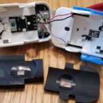
 The only difficulty in getting at the internals of the DVR were the security screws holding the case together. The security is more apparent than real in that the security torx heads necessary to do the job are readily available on Amazon.
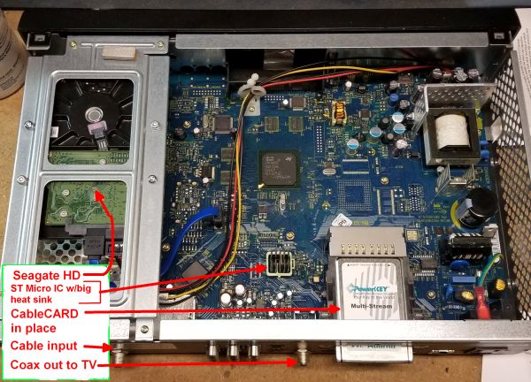
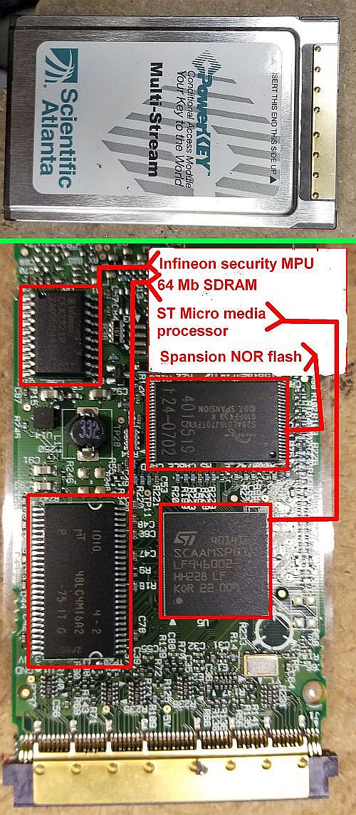
The physical CableCARD is a business-card-sized PCB that is inserted into a slot in the DVR. It serves to identify and authorize the customer and decodes the encrypted digital cable signal. Once the card has decrypted the signal, it provides an MPEG-2 transport stream to the DVR. The card also receives messages sent over the out-of-band signaling channel by the cable company and forwards them to the DVR. (As an aside, higher end TVs sometimes come with a cable tuner built in and include a slot for a CableCARD. As in a DVR, the card unlocks the channels and services to which the cable customer subscribes. TVs that support CableCARD this way are generally labeled “digital cable ready,” DCR.)
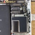
The cable signal goes through a lot of processing before it ever gets to the CableCARD. Starting at the cable input connector, the signal first goes through a Macom diplexer. The diplexer sends the incoming cable signal to a Skyworks active splitter (APS3606) which converts the signal into three RF signals that go to video tuner stages.
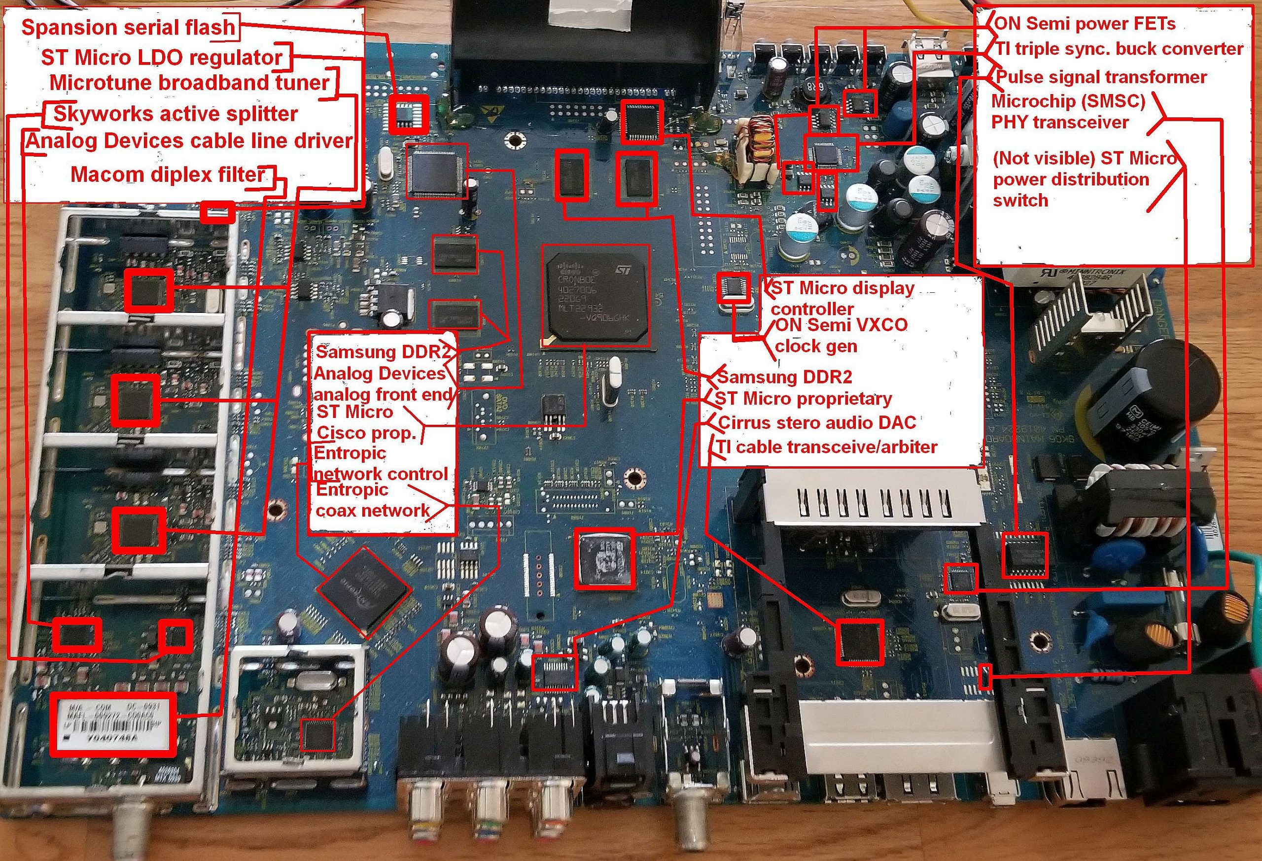
Data for the Ethernet connection seems to be handled by an Analog Devices analog front-end chip (AD9969JSTZ). There’s not much information available about this device other than that it contains two 12-bit and one 10-bit ADCs along with a 14-bit DAC.
The other output of the diplexer gets sent to three Microtune broadband tuners, each sitting in separate shielded areas on the PCB. These tuners (MT2022) each produce an IF in the 30 to 57 MHz range. These separate tuner stages are what let cable viewers record one channel while watching another—the DVR tunes to the channels of interest and uses the Microtune ICs to send the programming signals to demodulators. Two of the tuners are for displaying/recording while the third is for data networking. (This setup also illustrates why it would be tough to field a DVR handling more than two TV channels simultaneously; the tuner circuit for each channel takes up almost 3 in2 of PCB space. It would be tough to squeeze another tuner onto this architecture.)
The bulk of the signal processing and decoding takes place via private-label custom ASICs from ST Microelectronics. There are two custom ICs on the top of the PCB, one on the bottom. All seem to be from ST Micro. One of the ASICs apparently works pretty hard—it contains a beefy heat sink. These chips would necessarily handle the QAM demodulation, MPEG decoding, as well as other video processing and modem functions.
You can get an idea of some of the functions these chips handle from commercial versions. One is the STiH412 from ST Microelectronics. It contains a dual-core ARM CPU and a quad-core GPU and is designed to decode ultra HD.
The DVR’s VFD front panel is controlled by another ST Micro device (STM86312). An interesting point is that the DVR doesn’t contain a chip handling the IR signals from the remote. This leads us to surmise that one of the proprietary media processors assumes these chores directly.
The power supply section of the board is built around a Texas Instruments triple synchronous buck chip (TPS5130) so named because it converts 5.5 V into three other voltages. Some power FETs from ON Semiconductor comprise the other ICs in the power circuit.
Three other ICs round out the interesting part of the DVR circuit. A Cirrus CS4352 DAC/line driver puts out stereo audio for the speaker outputs. A Texas Instruments serial bus transceiver (TSB41AB1) sits underneath the CableCARD assembly and likely handles the communication between the card and the rest of the DVR.
Finally, a Texas Instrument TPS2041B power distribution switch sits next to the CableCARD assembly. TI says this chip is intended for applications where heavy capacitive loads and short circuits are likely to be encountered. It basically limits its output current when it senses a too-heavy load. Going by a reference design published by TI, this is probably part of the USB circuit.
And that’s about it for the Cisco DVR. Thanks for watching.


Leave a Reply