
A little toy made in China called the Induction crystal ball uses a pair of coaxial rotors to rise in the air, helicopter-like. It powers the rotors enough to rise for a few seconds, then cuts the power back to gently float down until a proximity sensor in the base of the plastic body comes  near the ground or your hand or some other object right below it. At that point, the power to the rotors gets boosted for a few seconds to let the toy rise again. You can repeat this sequence until the small lithium polymer battery runs out of juice.
The coaxial rotor setup this toy uses is common in inexpensive flying machines. In fact, the first teardown we did years ago had a coaxial rotor scheme resembling what we found here. It consists of two propellers mounted one above the other on concentric shafts having the same axis of rotation but turning in opposite directions. The formal name for this arrangement is contra-rotating. The benefit of having two coaxial sets of propellers, or rotors, is that they provide symmetrical forces around the central axis for lifting the toy off the ground. The resulting symmetry avoids the torque on the fuselage that arises if you only have a single set of rotor blades. When there is only one set of blades, the fuselage wants to spin in the direction opposing that of the rotor blades.
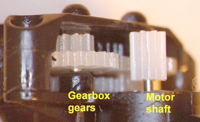
The downside of coaxial rotors in real helicopters is that the gearbox necessary for coaxial motion can get to be pretty heavy. You don’t have that problem in light-weight toys like this one where you can get away with using a completely plastic gearbox.
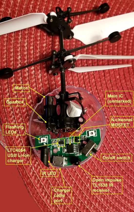
The vehicle electronics are pretty simple. A single eight-pin chip handles all the sensing and motor control and LED flashing. There are no markings on the chip so it’s probably a device made specifically for toys like this. The other semiconductors on the circuit board consist of a lithium battery USB charger IC from the Linear Technology operation of Analog Devices, an N-channel MOSFET from Siliconix, and an infrared receiver IC from Open Impulse in Hong Kong that detects reflections off surfaces from an infrared LED that’s aimed downward. The infrared LED and the infrared receiver together form a proximity sensor that signals the motor driver to boost the lift because the toy is too close to the ground.
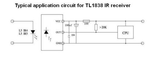 The typical application circuit for the infrared receiver IC includes a crystal, and the datasheet also says the chip uses a 38-kHz carrier frequency on its input. Interestingly enough, we didn’t find a crystal on the toy’s circuit board. So you might surmise that the main IC is generating the carrier for the IR LED, but without the benefit of a crystal. Consequently, the carrier frequency is probably drifting a bit, but that doesn’t seem to be important for floating a toy off the ground.
There are a few other circuit components on the board consisting of biasing resistors, capacitors, and the four LEDs that provide the light show. Rounding out what we found was a mechanical switch for turning the toy on and off, a jack that accepts a charging cable for the 75 mA-hr lithium-polymer battery, and of course, the electric motor.
All in all, an interesting way of making an inexpensive and amusing toy that flys.


I bought one of these for my nephew.
There were no instructions apart from what was on the box.
When switched on, the toy took off and ascended until it was out of sight and we never saw it again.
Unless there are other instructions that did not come with the unit I bought, I assume that the infra-red sensor malfunctioned.
Hilarious.
I bought one for my grandson and it doesn’t work. Can I get a replacement?
We have bought 2 sets of these and u can not take them outside to play cause as soon as they take lift off they go up and r gone never see them again even if u turn the controler off so the next set that he just got i told them to play in the house with them so they do not loose them
I need to find the IC of this toy, anyone can help me to find this IC?
I need the model and datasheet of this IC, if anyone know contact me via jalal.bakhtiari89@gmail.com .
Thank you very much
hey, nice review, but probably you forgot about charging indicator, it lights even if battery is cut off it