
The device which brings cable TV and high-speed internet into homes has a simple design but sports a couple of tricky secrets.
Lee Teschler
Executive Editor

If you’ve got broadband internet from a cable company, it comes into your house through a cable modem. Estimates are that some $8.6 billion-worth of cable modems will be sold by 2018 as next-generation gateways are introduced to manage Internet connectivity in the home. No question, then, that cable modems are important devices for connected homes. That’s why we decided to teardown a cable modem from Scientific Atlanta called the WebStar DCX2100.
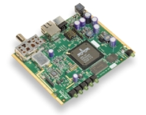
In our teardown series this may have been the easiest product to get apart. The case is just two pieces that snap fit together. The electronics all lies on a single circuit board. So disassembly consists of opening the case snap fits and unfastening the PCB from the case.
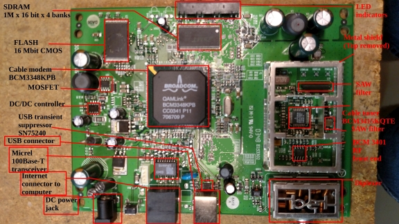
One big integrated circuit dominates the circuit board. It is a single-chip cable modem made by Broadcom. A lot of cable boxes use it. This particular chip is the BCM3348. It isn’t the most up-to-date version of Broadcom’s single-chip cable modem offerings, but the architecture of the hardware on this board isn’t much different from what would surround the latest and greatest versions.
 A lot goes on in the Broadcom chip. It implements what’s called DOCSIS 2.0. DOCSIS stands for data over cable service interface specification. That’s an international standard that lets cable TV systems transmit data as well as TV signals. The 2.0 version of the standard has been around for a while. The most recent version is DOCSIS 3.1.
Though it doesn’t implement the most recent version of DOCSIS, our teardown modem could still work on most U.S. cable systems. The 3.1 version of DOCSIS is for gigabit data streams, and only a few areas in the U.S. have it right now. The 2.0 devices handle datastreams in the range of tens of megabits.
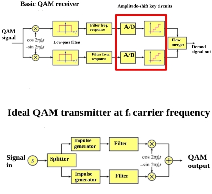
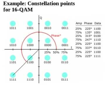
To manipulate data, the Broadcom chip uses a 200 MHz MIPS processor that implements quadrature amplitude modulation, or QAM. The inner workings of QAM is a big subject, but basically it is a scheme that conveys two digital bit streams by modulating the amplitudes of two carrier waves using amplitude-shift keying. The two carriers have the same frequency but are 90° out of phase with each other, which is why they are called quadrature carriers, hence the QAM acronym.
The modulated waves are summed to yield a final waveform that’s a combination of phase-shift keying and amplitude-shift keying. In the U.S., 64-QAM and 256-QAM are the mandated modulation schemes for digital cable. The 64 and 256 refer to the number of points in the QAM constellation diagram where each point in the diagram represents a specific digital number specified by a specific amount of amplitude and phase modulation.
Other chips
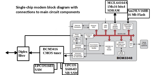
The cable modem chip connects to two memory chips, one a synchronous DRAM, the other a Flash. The flash chip lets the cable company change aspects of the subscriber’s internet service without actually changing any hardware. In that regard, the flash chip holds configuration data and comes into play, say, when a cable subscriber buys more download speed from the cable company. In this scenario, a signal gets sent down the cable that results in updated configuration data in the non-volatile flash memory.
There are a few other chips scattered around the PCB that aren’t all that interesting. One is a chip from Micrel used to handle the physical Ethernet interface for the cable. Another is a chip from Texas Instruments for suppressing voltage transients on the USB interface. And a dc/dc controller chip supplies the various dc rails the chips need.
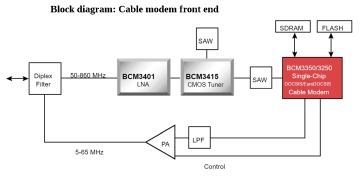 A more interesting part of the PCB sits in a metal enclosure close to the cable input. The metal enclosure keeps out electrical noise and probably also prevents the modem from radiating RF. That part of the circuit operates at a much higher frequency than the cable modem chip or the rest of the board — The cable company typically delivers frequencies to the modem that are in the range of 50 to 860 MHz.
There is a tuner chip in the shielded area that takes the incoming cable signals and reduces them to intermediate frequencies. The intermediate frequencies are in the 36 to 44 MHz range. Those intermediate frequencies get sent outside the metal enclosure to the cable modem chip.
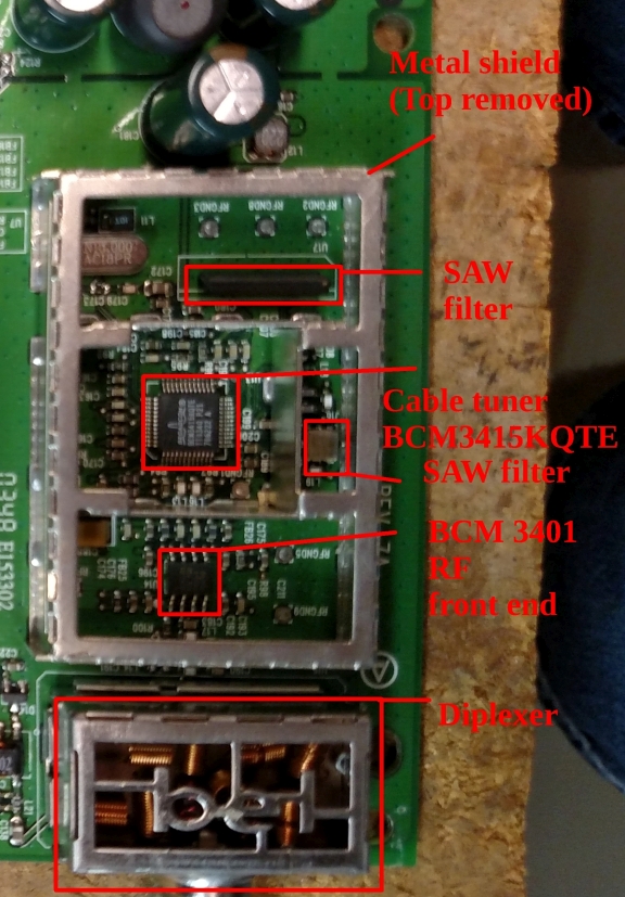
Also sitting inside the metal shield is one other main chip that sits in front of the tuner. It is an RF front end. It is basically a linear amplifier and provides a means of gain control for the incoming cable signal, compensating for variations in the strength of the signal coming in.
There are two other chips in the enclosure. They are both surface-acoustic wave filters which the cable tuner IC uses in producing the relatively narrow signals sent back to the cable modem chip.
Finally, there is a diplexer network sitting where the cable signal couples into the board electronics. The diplexer is passive in that it doesn’t use integrated circuits. It basically multiplexes two RF signals, from two different ports, onto a third port. In the case of the cable modem board, the diplexer network probably also performs some impedance matching, making the cable modem connection look like the same RF impedance as the incoming cable to maximize the power transfer from the modem box to the cable and vice versa.
The reason for the diplexer is that cable companies send data to the modem at between 50 and 860 MHz, but the cable modem sends back information in a different frequency band, between 5 MHz and 42 MHz. The diplexer is what lets the two signals coexist on the cable line. And it does so in a way that isolates the two signals from each other, so uploaded data doesn’t get sent back through the tuner chip.
It may be interesting to note that the next generation of cable modems may not bear much of a resemblance to our teardown device. Cable operators are moving to DOCSIS 3.1 advanced cable modem technology. DOCSIS 3.1 uses Orthogonal Frequency Division Multiplexing (OFDM) modulation. The OFDM scheme spreads aggregated IP traffic over several subcarriers that are between 10 KHz and 50 KHz wide. DOCSIS 3.1 will also be able to handle 4096-QAM in place of the existing 256-QAM. DOCSIS 3.1 also proposes to include electronics for allocating more spectrum to upstream traffic for better support of interactive applications. Experts say with appropriate planning, it should be possible for cable operators using DOCSIS 3.1 to deliver more than 100 Mbps downstream and 25 Mbps upstream to customers and to migrate TV signals to IP technology.
Another scheme in the works uses a standard proposed by the IEEE is called Ethernet passive optical network (PON) over Coax (EPoC). EPoC could potentially provide 10 Gbps speeds over the existing hybrid fiber/coaxial (HFC) architectures. This would use a new device sitting in local neighborhoods that would convert the communications on the fiber to separate Ethernet communications streams over the coaxial cable to each house. Users would access the EPoC system with a device resembling an optical network terminal, but with an RF coaxial network interface.
References
M12L64164A 1M x 16 Bit x 4 Banks Synchronous DRAM
BCM3348KPB QAMLink‚ DOCSIS 2.0 single-chip cable modem
Am29LV160B 16 Megabit (2 M x 8-Bit/1 M x 16-Bit) CMOS 3.0 V Boot Sector Flash Memory
MC34063A Unisonic Technologies dc to dc converter controller
LF-H41S Micrel 10Base-T/100Base-TX Physical Layer Transceiver
Texas instruments SN75240/SN65240/SN65220 USB Transient Suppressor
Would someone be able to use this as a device for stalking with adding a microchip in it? How would images on television change? Thanks
Probably not without a redesign.
What would it take to revive a Cable Modem which only light up at the press of the on/off button switch and then no-activity whatsoever?