• Skip to primary navigation
  • Skip to main content
  • Skip to primary sidebar
  • Skip to footer

Microcontroller Tips

Microcontroller engineering resources, new microcontroller products and electronics engineering news

  • Products
    • 8-bit
    • 16-bit
    • 32-bit
    • 64-bit
  • Applications
    • Automotive
    • Connectivity
    • Consumer Electronics
    • Industrial
    • Medical
    • Security
  • EE Forums
    • EDABoard.com
    • Electro-Tech-Online.com
  • Videos
    • TI Microcontroller Videos
  • EE Resources
    • DesignFast
    • eBooks / Tech Tips
    • FAQs
    • LEAP Awards
    • Podcasts
    • Webinars
    • White Papers
  • EE Learning Center

Teardown: The new Roku Ultra

December 1, 2020 By Lee Teschler 1 Comment

roku ultra
The Roku and remote. Below, with the rubber pealed off the bottom to reveal screws and a reset switch.

Roku bills its new Ultra device as its fastest and most powerful player ever. Its features include 50% more range for its wireless capabilities, support for Dolby Vision (an HDR standard), Dolby Atmos (a surround-sound format), and Bluetooth, a fast channel launch, a lost remote finder capability, voice-remote controls and personal shortcut buttons, and the ability to share videos, photos, and music from an Apple device using AirPlay (a streaming service).

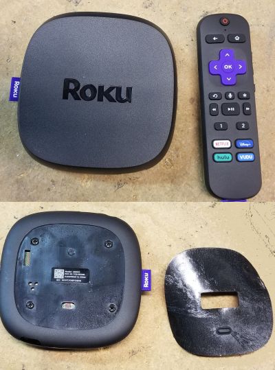
Those who compare the teardowns of previous-generation Roku devices with the new Ultra will notice several significant differences in the componentry. As with older devices, disassembly begins with pulling the rubber pad off the bottom of the Ultra to reveal four ordinary Philips screws. (Also beneath the pad is what appears to be a reset push-button which goes unmentioned in the Ultra instructions.)

roku case open
Note the two wire antennas and metal PCB antenna on the Ultra. Also, no aluminum heat sink on the case top. Click image to enlarge.
The first difference evident between this and previous generations of Roku devices is the heat sinking. Older Roku boxes had an aluminum piece screwed into the top half of the case. It provided a large heat-sink that cooled the main processor. The aluminum piece is gone from the new Ultra. Instead, designers used a smaller two-piece heat sink that fits on top of the metal shielding that protects the two SDRAM chips and the main display processor. Thermal grease connects the display processor to the heat sinking.

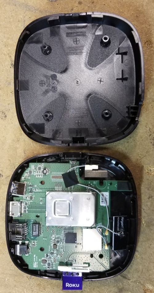
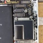
The other most evident difference in this edition of the Roku: The presence of three different antennas to handle the multiband WiFi and Bluetooth capabilities.

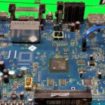
Most of the ICs on the Ultra come from Realtek in Taiwan. This is also a change in vendor from previous-generation

heat sink detail
The two-piece heat sink in stages of disassembly. Click image to enlarge.
devices. The main display processor carries a part-number of RTD1319VR. This isn’t a commercial Realtek device. The closest relative we could find is the RTD2662 series, a flat-panel LCD controller. It has some of the same features you’d expect to find in the Roku display processor, including support for an IR remote, HDMI processing, and an independent color processor. The Realtek display processor sits in a metal-shielded area together with two 8 Gb SDRAM chips from Nanya, a Taiwanese memory maker.

PCB top and bottom
The top and bottom of the Roku main unit PCB. The shielding on the bottom sat opposite the display processor and SDRAM on the PCB top side. Click image to enlarge.
The other memory chip on the Roku main board is a 5 GB Toshiba NAND flash. It has a Toshiba part number but evidently was manufactured in Taiwan, judging by its markings. This is where user settings and configuration data gets stored.

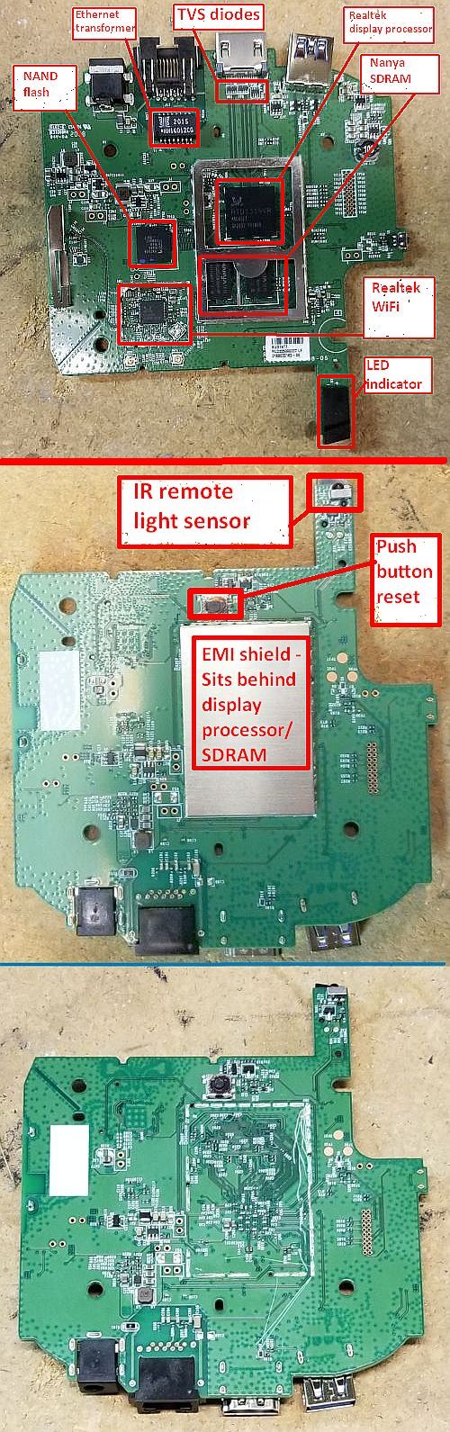
The final main chip on the Roku board is an RTL8822 multifunction WiFi SoC which sits in its own shielded enclosure. It’s data sheet says it contains both a 200-MHz Real-M300 CPU and a 20-MHz Real-M200 CPU to handle Wi-Fi, Bluetooth, Wireless MAC/baseband/RF, as well as audio codec features and configurable GPIOs.

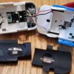
The IR remote unit for the new Ultra also looks quite different than previous models. It will obey voice commands, so

remote PCBs
Top, remote PCB front with buzzer still mounted in the plastic case. Middle, remote PCB back showing microphone. Bottom, the buzzer dissected. Click image to enlarge.
it includes a microphone that sits on the underside of its PCB. The main chip is a Realtek RTL8721DM. It’s description sounds similar to that of the WiFi/Bluetooth chip on the main Roku device, but it is specifically built to work as an HMI device. So it includes functions such as key scanning, IR signal handling, and an audio ADC. That said, it is interesting that we didn’t spot a discrete antenna on the remote. Apparently some of the conductive traces on the PCB double as antennas.

One last new feature on the remote is a buzzer-type assembly that sits in the top part of the case and connects to the PCB via a twisted pair. The buzzer/speaker serves two functions. It emits a tone as audible feedback when the user sets up personal shortcut buttons. It also helps locate the remote if it is lost between the couch cushions or if the dog has hidden it; Pressing a button on the Roku main unit actuates the buzzer.

There you have it. All in all, a lot of features built into the latest generation of streaming technology.

You may also like:

  • DVR
    Teardown: Cisco Explorer 8642HDC high-definition DVR with multi-stream cableCARD interface

  • Teardown — An oldie but still useful: The iPhone 6
  • pulse oximeter
    Teardown: A simple pulse oximeter for home healthcare
  • induction rotor toy
    Teardown: Induction crystal ball gyrocopter toy

Filed Under: Applications, Consumer Electronics, FAQ, Featured, Teardowns Tagged With: FAQ, nanya, realtek, toshiba

Reader Interactions

Comments

  1. Wonder Why says

    December 11, 2020 at 12:54 pm

    I wonder why people including me come to look at these tear downs? They are all just a few PCB’s with surface mount components on them and will be in the trash can in 24 months. Another one of life’s minor mysteries.

    Reply

Leave a Reply Cancel reply

Your email address will not be published. Required fields are marked *

Primary Sidebar

DesignFast

Component Selection Made Simple.

Try it Today
design fast globle

EE Training Center Classrooms

“ee

“ee

“ee

“ee

Subscribe to our Newsletter

Subscribe to weekly industry news, new product innovations and more.

Subscribe today

RSS Current EDABoard.com discussions

  • Why will at low temperature Corner point Analysis( in cadence Virtuoso) fails?
  • 32kW peak power in inrush NTC
  • How to include a modification in a PIC dev board with PIC16F877A for OVP ?
  • Whate happening if connected DC Reactor to braking resistor ?!?
  • 2kW Step-down PWM converter for high voltage dc-BUS

RSS Current Electro-Tech-Online.com Discussions

  • Touch circuit sound, led. 555 timer
  • Array of pointers to 16 series port SFRs.
  • Automotive 6 Volt Generator Transistor Voltage Regulator
  • Random noise generator calibration
  • Neon sign transformers for Tesla coil

Follow us on Twitter

Tweets by MicroContrlTips

Footer

Microcontroller Tips

EE World Online Network

  • DesignFast
  • EE World Online
  • EDA Board Forums
  • Electro Tech Online Forums
  • Connector Tips
  • Analog IC Tips
  • Power Electronic Tips
  • Sensor Tips
  • Test and Measurement Tips
  • Wire and Cable Tips
  • 5G Technology World

Microcontroller Tips

  • Subscribe to our newsletter
  • Advertise with us
  • Contact us
  • About us
Follow us on TwitterAdd us on FacebookFollow us on YouTube Follow us on Instagram

Copyright © 2021 · WTWH Media LLC and its licensors. All rights reserved.
The material on this site may not be reproduced, distributed, transmitted, cached or otherwise used, except with the prior written permission of WTWH Media.

Privacy Policy