The mmWave equipment on connected vehicles may sport dielectric resonator antennas that look nothing like conventional antennas.
Automotive designers have always put a premium on technologies that are light-weight and compact. The preference hasn’t changed for connected vehicles. As connected features increasingly rely on mmWave frequencies, designers investigate ways of shrinking the size of radio frequency (RF) electronics. In that regard, various antennas relying on monopoles, dipoles, and patch antennas have been proposed for millimeter-wave use. However, these antennas typically have radiation efficiency problems and a narrow impedance bandwidth because of lossy silicon substrates.
Enter the dielectric resonator antenna (DRA). It typically has a puck-shaped cylindrical shape rather than the radiating elements of the typical antenna. DRAs experience no conduction losses and can be highly efficient radiators. The first DRAs made use of ceramic materials characterized by high permittivity and a high Q (between 20 and 2,000). More recent DRAs are plastic poly-vinyl-chloride, PVC.
DRAs are specialized versions of dielectric resonators. The dielectric material has a large dielectric constant and a low dissipation factor. (Recall that dissipation factor is the reciprocal of the ratio between the material capacitive reactance and its resistance at a specified frequency.) The resonant frequency is determined by the overall physical dimensions of the resonator and its dielectric constant. In a dielectric resonator, the RF is confined inside the resonator material by the abrupt change in permittivity at the surface so RF waves bounce back and forth between the sides. At the resonant frequencies, standing waves form in the resonator, oscillating with large amplitudes.
Thus dielectric resonators resemble cavity resonators in their behavior. Cavity resonators are hollow metal boxes employed as resonators at microwave frequencies. Here RF reflections are via the large change in permittivity rather than by the conductivity of metal. Metal cavity resonators don’t work at millimeter wave frequencies because in this frequency range their metal surfaces become lossy reflectors.
Also of note is that while the electric and magnetic fields are zero outside the walls of a metal cavity, these fields are not zero outside the dielectric walls of the resonator. Even so, electric and magnetic fields decay considerably from their maximum values away from the resonator walls. Most of the energy is stored in the resonator at a given resonant frequency.
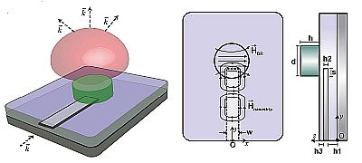
There are three types of resonant modes in dielectric resonators: transverse electric (TE, a magnetic field only along the direction of propagation), transverse magnetic (TM, the magnetic field is crosswise to the direction of propagation while the electric field is normal to the direction of propagation), or hybrid electromagnetic (HEM, both electric and magnetic fields have a component in the direction of propagation) modes. Theoretically, there is an infinite number of modes in each of the three groups, and desired mode is usually selected based on what the application needs.
To see why DRAs can be smaller than conventional antennas, consider that a metallic antenna size is proportional to the wavelength of its resonant frequency in free space. In contrast, the size of a DRA is proportional to the free-space wavelength divided by √ϵr where ϵr is the relative permittivity of the DRA material. Thus to shrink the DRA, use a material having a high ϵr. The use of a low-loss dielectric material also gives DRAs their high radiation efficiency. And a DRA antenna can be made with a relatively large bandwidth by adjusting the dimensions of the device and the material dielectric constant.
The resonant frequency of the modes that a given cylindrical DRA supports is a function of the resonator height, radius, and dielectric constant. The equations for specific resonant frequencies involve roots of Bessel functions and their derivatives. Bessel functions are a standard solutions of a differential equation known as Bessel’s differential equation. Bessel functions are often described as a way of describing vibrations in a medium with variable properties, which is why crop up in describing DRAs.
Though cylindrical DRAs are probably the most widely used, rectangular DRAs are also common. The main advantage of the rectangular shape is that it offers more design flexibility than cylindrical types through adjustments to height, length, and width dimensions. Rectangular DRAs also have less cross-polarization than cylindrical types. (Cross Polarization is the
polarization orthogonal to the desired direction. If the antenna field are meant to be horizontally polarized, the cross-polarization direction is vertical. If antenna waves are right-hand circularly polarized, the cross-polarization is left-hand circularly polarized, and so forth.) The DRA resonant frequency in this case is a function of the square-root of the sum of the length, width, and height dimensions.
It is as well possible to find hemispherical and cross-shaped DRAs and DRA arrays. Cross-shaped DRAs tend to be used to obtain circularly polarized waves. Arrays of cross DRAs can be used to get a larger antenna bandwidth.
Similarly, what are called super-shaped DRAs can be found. These are DRAs with a more complex 3D shape, usually done as a way increase the antenna bandwidth. An example of a supershaped DRA might be one where the basic shape is cylindrical but instead of a curved side, there are eight flat sides.
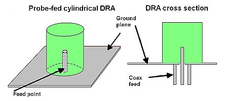
One aspect of DRA technology is that specific radiating modes can be excited depending on where RF is fed into the DRA device. (Probe-fed DRAs aren’t practical when the DRA is made on a PCB or is integrated on an IC.) Probably the most common configuration for discreet DRAs is that where the DRA sits on a ground plane and is excited by a coax cable fed through the substrate. Interestingly, the coax probe can penetrate the DR but it can also be placed directly next to it. Adjusting the length and position of the feeding probe tunes both the input impedance of the DRA and its resonant frequency.
The main benefit of using a probe feed is that it couples a high amount of signal into the DRA which, in turn, leads to high radiation efficiency. The down-side of this approach is that a hole must be drilled into the DRA material that precisely matches the length and radius of the probe. Slight mismatches can change the dielectric constant of the resonator and shift the antenna resonant frequency. Placement the probe next to the DRA, rather than inside it, is less sensitive to dimensional mismatches but couples less signal into the antenna.
Another way to feed the DRA is via printed transmission lines. In conventional microstrip line-fed DRAs, the dielectric resonator sits directly on the transmission line printed on the PCB substrate. The overlap distance on the printed conductor determines the coupling strength and the specific transmission mode that is excited. The strongest coupling is when the overlap distance is slightly shorter than one-quarter wavelength of the dielectric resonance frequency.
The main drawback of the microstrip transmission line feed is that the transmission line is not isolated from the DRA which can affect the radiation performance of the DRA. Also, when the dielectric resonator sits on the top of a transmission line, there’s an air gap between the resonator and the PCB substrate which can degrade antenna performance.
The other way of devising a microstrip transmission line feed is to place the DRA on the PCB and extend the PCB transmission line trace from the board to one of the outer sides of the DRA. This approach eliminates the air gap arising when the DRA sits on the microstrip transmission line. The shape of the transmission line can be optimized to improve the DRA performance, usually in terms of the antenna bandwidth.
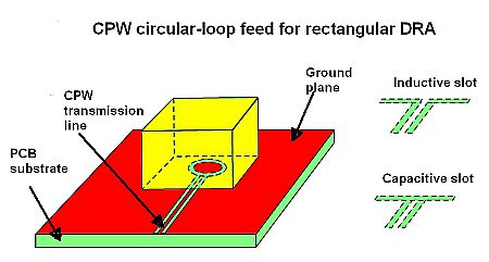
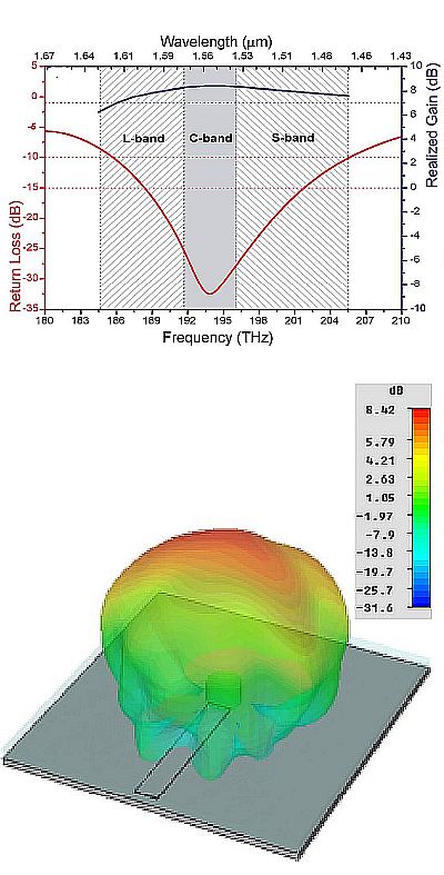
Another approach is the coplanar-waveguide (CPW)-fed DRA. The coplanar waveguide can take the form of a circular-loop or capacitive or inductive slot feed. The main advantage is that tweaking the coupling slot underneath the DRA can optimize the DRA performance. A capacitive slot, for example, can add a resonance so one resonance is associated with the DRA, another with the feeding slot itself. CPW feed structures are widely used for mmWave applications because the PCB ground plane separates the dielectric resonator from the lossy silicon substrate to yield high antenna efficiency.
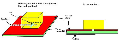
The most widely used feeding technique for DRAs is via a slot in the ground plane, a method known as aperture coupling. Here the DRA sits on top of the PCB microstrip transmission line and there is a slot in the PCB ground plane that also sits under the DRA and is oriented at 90° to the transmission line. Energy from the transmission lines couples through the slot to the resonant modes of the DR.
The best resonance (impedance matching) takes place with the DRA perfectly centered on top of the slot. The main advantage of this method is that it avoids a direct electromagnetic interaction between the feed line and the DRA which reduces spurious radiation from the feeding network and boosts the polarization purity of the DRA. The drawback of this approach is that it becomes impractical at lower frequencies; the slot length should be around a half-wavelength long at the resonant frequency, challenging at lower frequencies when the DRA must remain compact.
In general, the size of the DRA is inversely proportional to the dielectric constant () of the resonator material. But use of a high also tends to limit antenna bandwidth. Multilayer DRA topologies are sometimes used to mitigate the bandwidth problem by optimizing the and height of each layer.
Some DRAs also contain a conducting plate strategically placed as a means of reducing antenna size. On a rectangular DRA, for example, a conducting plate might go on one of the outside antenna surfaces. The price paid for the size reduction is typically a reduced antenna bandwidth.
Another way of getting more gain out of a given DRA is to excite it at a higher-order resonant mode. This makes the DRA electrically larger with respect to its fundamental resonant frequency.
References
Wikipedia dielectric resonator antenna page,