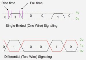
Differential signaling is used in many communication schemes including HDMI, USB, DVI, CAN, LVDS, and more. Differential signaling uses two wires and therefore two signals accomplish transmitting a series of bits from one point to another. In the figure below, the first image demonstrates single-ended signaling, which uses a single wire and pulses 0s and 1s on that wire to get a serial string of bits to the receiver. Logic 1s and 0s are read at the receiving end, but practically speaking these are not crisp step functions, there is a rise time for each signal to reach the high of a logical 1, and a fall time for each signal to make a low of logical 0. The single-ended signal flows from sender to receiver and the signal-carrying current then sinks into a ground plane, for example, and flows back to the sender through a ground plane (or similar path.) An example of single-ended signal transmission is RS-232 serial communication.

The second image shows two wires, one whose signal is represented in black, the other in red. Each wire has its own separate signal, except one wire is set up to always show the exact opposite signal of its companion wire. The signals are balanced in that they have equal amplitude. The receiver has a differential amplifier that receives the signal as the difference in voltages it sees on the two wires. Theoretically, there is no total current flow in the twisted pair of a differential signal because the amplitudes cancel each other out. This means that ground is less important, but most communication using differential pairs will include a ground wire to maintain a reference to refrain from having signals go beyond specified boundaries. Signals are not subject to local ground disturbances when passing from one PCB to another, for example. Current flows in opposite directions through the differential pair rather than a ground wire; current does not flow to ground (ideally). Since currents flow in opposite directions in a differential signal pair, the magnetic flux gets cancelled and EMI noise from signal harmonics is lower
In the above diagram, the black line shows the signal and the red line shows the complementary (opposite) signal. When the signal gets transmitted, any external noise will affect both wires equally in the differential pair. The difference amplifier on the receiving end rejects common signals, so noise riding the signals can be identified and rejected. Common mode noise is possible and can be reduced by using chokes wherever a differential signal enters or leaves a board to filter noise, but only if EMI is a real problem.
Differential signaling is more immune to noise and it is faster. The difference in voltage level between the two signals is what determines whether the pulse is a 1 or a 0. There is still a rise and a fall time associated with each signal, but differential signaling can have lower voltages and a faster switching time. Lower voltage also equates to lower overall power consumption. Reducing the amplitude of the voltage in the signal requires less rise and fall time to reach and return from logical 1. Therefore, differential signaling is better for higher speed transmission than single-ended.

Leave a Reply