
A capacitor behaves like an open circuit at DC voltages. (Recall that DC is voltage that operates at a frequency of 0 Hz, which is a flat-line voltage of varying heights or levels). If there’s an AC (varying) component or noise in the signals traveling in the circuit, then as the frequencies of the varying signals increase, capacitors in the circuit begin to act like a short circuit, thus the name “bypass capacitor.” A capacitor can be placed in the circuit in a location that will suppress, or “bypass” signals, removing signals that you don’t want (usually by bypassing them to ground). See Figure 1. Most digital electronics circuits operate on DC voltages. Microcontrollers (MCUs) operate on DC voltage levels, and the real-world analog signals coming in from external sensors (e.g., temperature) get converted to digital (DC) signals before getting processed. However, real-world noise is rarely purely digital (i.e., a binary, DC-type signal); real-world noise has a frequency (i.e., varies/wiggles/has spikes).
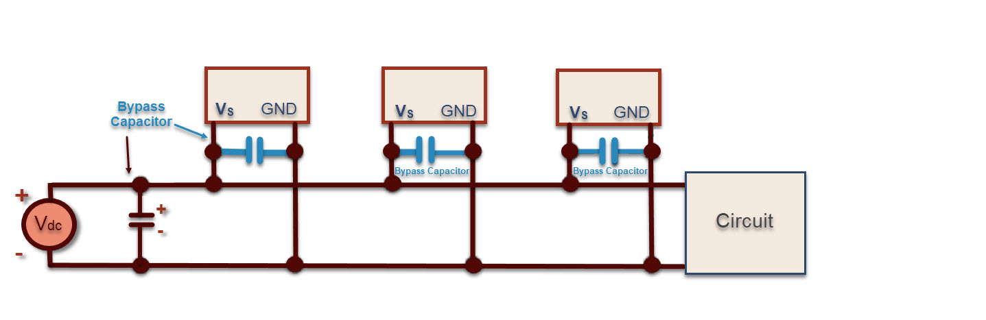
Per the dictionary of Electronics, a bypass capacitor, also referred to as a decoupling capacitor, is “a capacitor employed to conduct an alternating current around a component or group of components. Often the AC is removed from an AC/DC mixture, the DC being free to pass through the bypassed component.” Very often, bypass capacitors are used to filter out noise from a power source that supplies a circuit. For this purpose, you can think of the bypass capacitor as a frequency-dependent resistor. Noise is usually completely unpredictable and changes in nature after a Printed Circuit Board (PCB) leaves the test bench in the factory. For frequencies less than 50 MHZ, a bypass capacitor value of 0.1 µF or 0.01 µF is placed close to an integrated chip’s voltage supply and ground pins. (Placing them farther away from the power/ground pins results in unwanted inductance and resistance.) Per an Intel document section on decoupling technologies, “The closer to the load the capacitor is placed, the more inductance that is bypassed. By bypassing the inductance of leads, power planes, etc., less capacitance is required. However, closer to the load there is less room for capacitance.”[i] Bypass capacitors are all about keeping the power supply even. Electrons are continually being recycled through the ground plane, but flow can seem unpredictable if unseen but inherent resistance and inductance are scattered about in a network all over the system or PCB. An MCU or processor has several voltage power rails that supply various loads. The loads dynamically consume power and bypass capacitors reduce instances of current spikes or starvation in the power supply rails.
Bypass capacitors also filter out noise. In the real world, noise can come from anywhere; it can be introduced electrically, from magnetically induced currents, from nearby mechanical (purely physical) vibration, and myriad other sources. In an ideal world, you would not need a bypass capacitor, because you would not have noise in a perfect world. A powered circuit has a voltage supply from a battery or power supply, so current is flowing and power is getting consumed if the circuit has a load (is doing work). In an ideal world, with an ideal chip, bypass capacitors are not necessary because the chip would get precisely 3.3 volts on the voltage supply pin. However, in the real world, the Printed Circuit Board (PCB) traces, wires, component pins, connectors, and cabling possess an inherent resistance and inductance. Each is small in value but all add up to enough to affect the flow of current and thus, circuit signal behavior. Inductors resist change in current flow, which gets worse as the frequency of a signal gets higher. As the frequency of the signals that you are working with get higher, rapid changes in current flow within your circuit are influenced by the inherent inductance of the various wires and traces.
At frequencies approaching or above 50 MHz, you will often see multiple bypass capacitors, since this technique works best if you distribute the decoupling capacitance effect. With higher frequencies (500 MHz > f > 50 MHz,) using several small capacitors placed around a chip will lower the total inductance.[ii] You can even outflow of current and distribution of power with decoupling capacitors that are evenly spread out across a board. At even higher frequencies, specialized techniques with PCB layers might be employed.
The term bypass/decoupling for a capacitor is purely a description of how the capacitor is being used. The function to bypass noise to ground can be accomplished by any type of capacitor (e.g., electrolytic, ceramic, film, etc.). Don’t confuse the bypass or decoupling function of a capacitor with a coupling or blocking capacitor. A coupling or blocking capacitor is used in a circuit to control what’s going on in a mixed signal circuit. That is, a capacitor used to couple and block a signal can be used to connect two circuits by letting only the varying portion of the signal from the first circuit through to the other circuit while blocking the average dc level of the signal.)
[i] https://www.intel.com/design/pentiumiii/applnots/24508501.pdf
[ii] http://www.hottconsultants.com/techtips/decoupling.html
This is actually a really well done explanation of capacitors and why they are necessary. Thanks for making it make sense a bit more to those who may only use components based on a data sheet instead of grasping the fundamental reasoning. I am guilty often, but my circuits usually work out in the end by the time I let myself learn why components are being used :>