Over-the-air testing requires different antenna setups for 5G FR1 and FR2. Temperature is a significant factor in calibration and validation.
While 5G is bringing changes for consumers and businesses, it’s also bringing changes for engineers. The tight integration in 5G user equipment means that wired testing is no longer viable. Thus, over the air (OTA) testing is now essential. How you set up these tests greatly affects test results. Temperature plays a role, too.
In 3G and earlier wireless networks, wireless terminals, handhelds, cell phones, and UEs were tested using hard-wired or cabled connections. This was sufficient because the main cause of transceiver failures were high mobile speeds (also known as Doppler effects) causing shorter coherence times (the time when a channel is constant). This produced estimation errors and a high delay spread, which caused inter-symbol interference due to large echoes of the signal. None of these issues are antenna dependent.
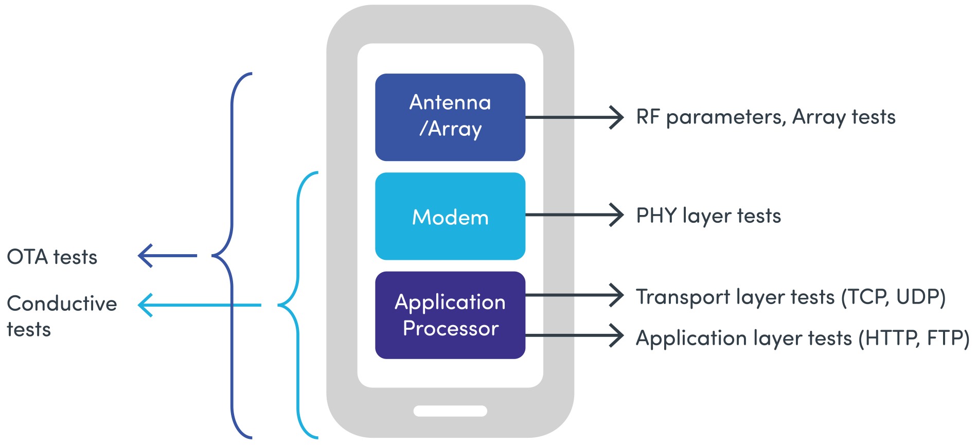
4G introduced multiple input-multiple output (MIMO), an antenna technology where multiple antennas appear at both the source (transmitter) and destination (receiver). On top of the Doppler and delay spread, a device’s transceiver needed testing against correlation: a metric of how well two or more signals can be separated in the same frequency band. Correlation is a function of the antenna and propagation, thus in addition to propagation, tests must include the antennas. Therefore, over-the-air methodologies (Figure 1) became mandatory to test these devices.

Figure 1. OTA tests the entire device performance whereas conductive tests are a subset of OTA tests, omitting antennas and antenna arrays.
In 5G, the antenna is even more predominant because of massive MIMO, which uses the spatial domain to deliver the signal. Therefore, antennas (now an antenna array) are an integral part of the transceiver performance.
What is MIMO OTA Testing?
MIMO over the air (OTA) testing lets engineers test a device in a controlled and accurate environment by subjecting it to a realistic propagation environment that encompasses temporal and spatial dispersion. MIMO OTA is the only way to holistically test a device. 5G MIMO OTA is subdivided into two main categories: FR1 (Frequency range 1, fc at or below 7.125 GHz) and FR2 (Frequency range 2, fc at or above 24.25 GHz). In both cases, a MIMO OTA test system consists of the following components:
- A network emulator, capable of making an active connection to the device under test (cell phone, tablet),
- A 5G channel emulator, capable of creating the desired propagation environment,
- Power amplifier modules,
- Frequency converters (for FR2)
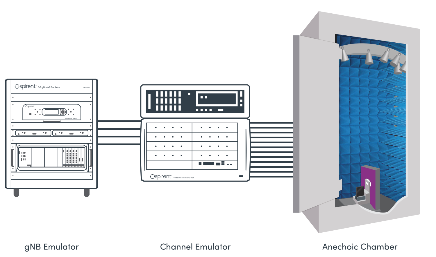
- An anechoic chamber. A simplified schematic is shown in Figure 2.

Figure 2. A typical FR2 MIMO OTA system includes a gNB emulator, channel emulator, and anechoic chamber with the device under test.
Critical to the design of such a chamber is correct radiator antenna probe placement. Probe locations (and power weights) are defined by propagation models. In industry standards, a subset of 5G channel models is used to optimize the probe locations to create the appropriate signal distribution in space [Ref. 1]. Thus, designing a MIMO OTA system always requires a deep understanding of radio channel modelling [Ref. 2].
Testing 5G NR FR1 vs. 5G NR FR2
In 5G NR FR1, MIMO OTA tests are compatible to 4G tests; the only difference is that the probe layout is a 2D ring using 16 dual polarized probes in a circle, while 4G MIMO OTA uses eight dual polarized probes in a 2D ring (Figure 3). The main motivation of this choice was the compatibility to 4G and the fact that 5G NR FR1 devices are primarily used in MIMO mode, not beamforming mode. The key device performance characterization metric, or figure of merit (FoM) used in both 4G LTE and 5G NR FR1 is spatial correlation. FoM is function of angular spread and antenna array element orientation and separation.

Figure 3. 2D probe layouts for 5G NR FR1 and 4G LTE MIMO OTA testing show how 5G needs more locations.
In 5G NR FR2, the probe layout is completely different due to design around a different FoM called power angular spectrum similarity percentage (PSP), which expresses the beamformer’s ability to estimate the appropriate power angular spread. PSP characterization can be achieved in a much smaller footprint and results in the configuration of a 3D wall optimized to support two channel models from the the appropriate signal distribution in space. The layout is heavily affected by gNodeB beamforming. A typical gNodeB is an 8×16 array, which results in high spatial filtering when applied to any channel model. After this spatial filtering occurs, only 1-2 clusters remain. Therefore, only a small wall is sufficient for probe placement and the size of the associated chamber is also relatively small. If a device under test is placed in radiated near field conditions, only nulls are affected (Figure 4). Many studies show that a 75 cm distance is sufficient to accurately test a handheld device with this method [Ref. 3].
MIMO OTA test system design
In the design of any test system, the first thing to consider is link budget. That is, does the device under test and the network emulator get sufficient power levels to receive and decode the signal and is there enough margin to vary the signal levels? In OTA tests, the main consumer of the link budget is the air link between the probe antenna and device under test. Thus, you need a power amplifier to compensate for the large air loss. This is specifically important in a 5G NR FR2 system, where path loss is very high.
Next, you must choose propagation models. The propagation models define how the probe antennas are distributed and weighted in the chamber. The original model needs mapping to a spatially discretised probe-antenna constellation. This requires a deep understanding of the channel models and how to translate that into chamber design.
The system needs calibration and validation. Calibration ensures alignment of phase and amplitude in the test volume (area where the device under test is placed). Calibration is time consuming and requires expertise on using the instrumentation. Validation, on the other hand, is the process that verifies the system creates the desired propagation conditions (level, polarization, temporal, and spatial aspects) in the test volume. Both system understanding as well as propagation testing skills are needed for this exercise.
Typically, a MIMO OTA system is unidirectional, meaning only downlink signals are faded. That’s because MIMO OTA stresses the device receiver. Uplink signals aren’t faded, simply because your goal isn’t to test the network emulator. It is, however, mandatory to have an active connection to the device under test. Thus, both the uplink and downlink must be part of the test system. How, then, do you separate the uplink from the downlink in the system?
For FR1 tests, you should use a communication antenna located close to the device under test. Engineers have used this method for many years with 4G MIMO OTA testing. For 5G NR FR2, however, the device under test uses beamforming. Signals from the DUT are spatially selective and some directions are less favorable for establishing a connection than others. Thus, you can no longer use a single (or dual) communication antenna for the uplink. Instead, you must use multiple antennas to establish the uplink connection. Alternatively, you can use the same antennas for the uplink and downlink, but that requires precise timing to switch between the two directions. In principle, the switch should be synchronized to transmitted slots and must be configured to different uplink and downlink transmission structures (i.e., heavy downlink traffic, heavy uplink traffic, balanced traffic).
Next, you must consider phase drift over the time. All instruments in the test system should connect to the same master clock (or 10 MHz reference signal). Doing so becomes important in 5G NR FR2 because the DUT uses a beamformer. Beamforming results from controlling the phase (and amplitude) of the transmitted signal, thus any phase change in the test system will modify the received signal. Therefore, you must ensure that phase is stable over time, with no drift introduced; this is addressed as part of the system validation and bring up. At Spirent, we found that temperature is the most important factor in maintaining phase stability. If the room temperature remains constant, the phase will remain stable for days. Temperature is the main reason for abrupt phase changes in instruments.
Lastly, all MIMO OTA test systems need software, commonly known as the test executive. The test executive not only takes care of running the test cases, but also calibration, validation, progress monitoring, reporting test results, and informing the user of any failures.
Tests and Results
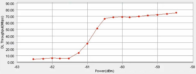
Typical FR2 MIMO OTA tests cover throughput vs. power (i.e., energy per resource element or EPRE) and throughput vs. signal over interference and noise ratio (SINR) with varying channel models. The plot in Figure 5 shows how the throughput increases as power level increases until reaching a plateau.
The architecture of a MIMO OTA test system is determined by the target frequency range. With 5G NR FR1, the test chamber size is large (roughly 16 ft W x 10 ft H x 16 ft D or 5 m x 3 m x 5 m) and typically requires customized construction and a great deal of space to be accommodated. Therefore, a system integrator typically needs to lead the delivery. However, with 5G NR FR2, the chamber size is relatively small (roughly 3 ft W x 4 ft H x 2 ft D or about 1 m x 1.2 m x 0.6 m) so that the complete system can fit into a standard lab space.
References
1. Standard 5G channel propagation models are defined in several 3GPP specifications, dependent upon the frequency range and environment of interest – https://www.3gpp.org/specifications-groups/ran-plenary/ran4-radio-performance-and-protocol-aspects
2. J.P. Nuutinen, D. Reed, A. Rodriguez-Herrera,”5G MIMO OTA Testing on Frequency Range 2 (FR2)”, URSI GASS 2020, Rome, Italy http://www.ursi.org/proceedings/procGA20/papers/URSIGASSSummaryPaperNuutinenReedHerrera.pdf.
3. 3GPP RAN4, “R4-1915062 Range length and probe layout considerations in 5G NR FR2” Spirent Communications, November 2019, Reno, TX https://portal.3gpp.org/ngppapp/TdocList.aspx?meetingId=32851.
 Jukka-Pekka (JP) Nuutinen is an industry-renowned subject matter expert in radio channel emulation with over 20 years of experience in engineering and research and is currently focused on cellular base station (gNodeB) and device test methodology for 5G technologies. Born in Valkeakoski, Finland, JP holds both Masters and Licentiate Technology degrees from Tampere University of Technology. He has more than 20 granted patents in addition to over 30 authored or co-authored publications.


