Digital predistortion compensates for an amplifier’s nonlinearities, letting it operate in its nonlinear region for maximum power efficiency.
Power amplifiers (PAs) are indispensable components in a wireless communication system. Unfortunately, they’re inherently nonlinear. This nonlinearity generates spectral regrowth, leading to unwanted radiation and adjacent-channel interference. It also causes in-band distortion, resulting in degradation of its error vector magnitude (EVM) performance. To improve EMV, a PA’s operating point needs to be backed off far from its saturation point, leading to very low power efficiency, typically less than 10%. Thus, more than 90% of the DC power gets lost, turned into heat. Considering the large number of wireless base stations deployed worldwide, improved PA efficiency could substantially reduce the electricity and cooling costs incurred by cellular operators.
Digital pre-distortion (DPD) provides an effective method to linearize PAs. DPD lets cost-efficient nonlinear PAs run in their nonlinear regions with minimized distortions, resulting in higher output power and greater power efficiency. The concept is based on inserting a nonlinear function (the inverse function of the amplifier) between the input signal and the amplifier to produce a linear output. The DPD must adapt to variations in PA nonlinearity with time, temperature, and use of different operating channels.
This article describes the DPD concept and its effectiveness at improving PA efficiency. It also discusses some of the DPD challenges to improve the power efficiency in 5G systems.
What is digital predistortion?
DPD operates in the digital baseband domain, offering lower implementation complexity than alternative techniques such as feedforward linearization, which operates in the RF domain. DPD lets cost-efficient nonlinear PAs operate at higher output powers and into their nonlinear regions with minimized distortion, resulting in greater power efficiency.
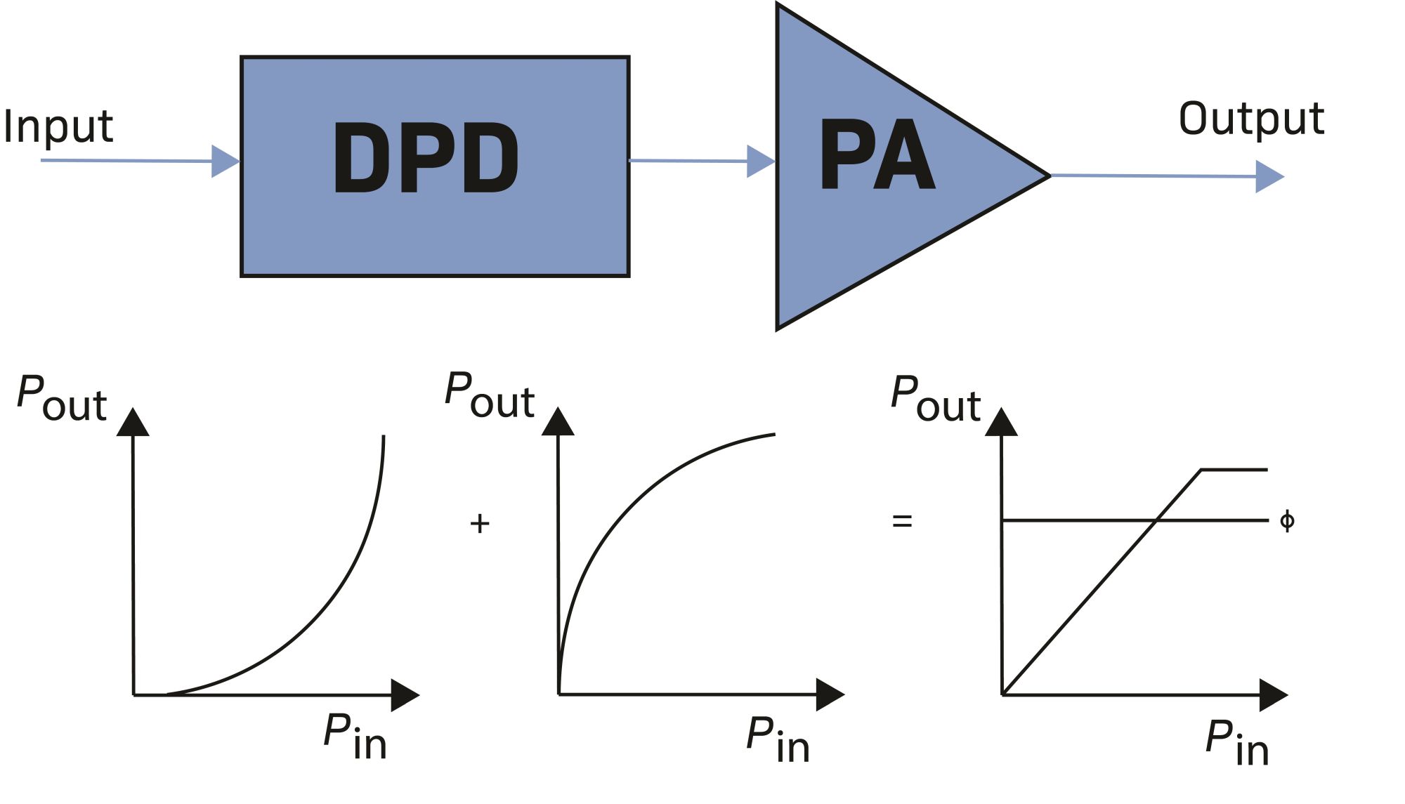
Figure 1. Block diagram of a DPD system shows how it linearizes the PA.
The DPD is equivalent to a nonlinear circuit with a gain expansion response that is the inverse of the power amplifier gain compression (AM/AM) and a phase rotation that is the negative of the PA phase rotation (AM/PM) as shown in Figure 1.
DPD must adapt to variations in PA nonlinearity. Another challenge of DPD is the dependence of the PA’s transfer characteristics on the signal’s frequency content, defined as changes of the amplitude and phase in distortion components based on past signal values. These are typically referred to as memory effects. In addition to the correction of the PA nonlinearity, memory effect compensation is an important requirement of the DPD algorithm especially when the signal bandwidth increases.
Most adaptive DPD blocks adapt to the slow variation of PA characteristics. The fast variation is, however, typically not taken into consideration. Attempting to compensate for the fast variation of PA characteristics or short-term memory effects with conventional DPD (based on Taylor series) schemes can degrade the performance or even make the system unstable. The DPD techniques to use are based on subset of the Volterra series memory polynomial and generalized memory polynomial. The nonlinear correction may be applied to the complex baseband signals using any suitable form of digital signal processing, including both real and complex domain (I/Q or polar) processing. Preferably, the nonlinear correction is applied using a parallel processing architecture, whereby two or more samples are processed simultaneously, to accommodate the high sample rate of the expanded bandwidth.
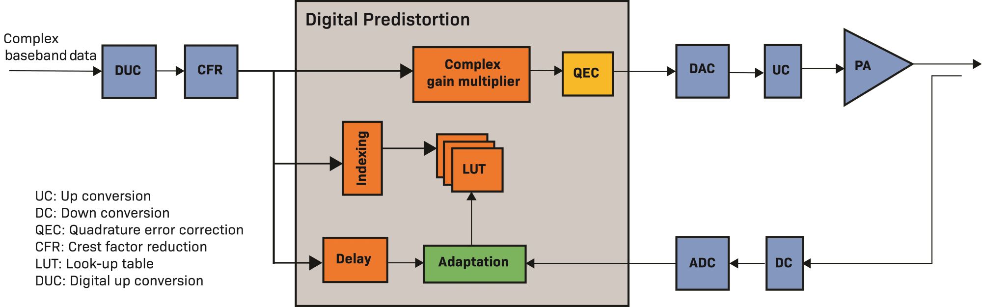
Figure 2. A transmitter’s DPD block resides between the crest-factor reduction block and the DAC/ADC functions.
Figure 2 shows the functional blocks of an adaptive DPD in the transmit chain of a typical communication system. The DPD subsystem consists of different blocks including a DPD model look-up table (LUT), a complex gain multiplier, and an adaptation block. Following digital up-conversion (DUC), the signal peak-to-average ratio (PAPR) is reduced using a crest-factor reduction (CFR) technique. CFR also plays a key role in improving the PA efficiency by reducing the back-off. Most systems apply DPD to the digital baseband signals immediately after the CFR block. Without CFR in the system, the PAPR after DPD will increase. That could cause instability in the DPD algorithm convergence. The DPD training at system startup occurs from collecting the PA samples from the observation path with CFR is disabled. This allows the system to obtain the PA’s full characteristics for DPD training.
The other block in Fig. 2 is the quadrature error correction (QEC). Due to the imperfections in the local oscillator (LO) in the up-conversion (UC) block and digital to analog converter (DAC), the IQ imbalance occurred, which requires compensaton in QEC.
How does DPD improve PA efficiency?
PA efficiency in communication systems is one of the most important factors for prolonging battery life and minimizing system costs. PAs are typically the most power consuming components in communication systems and can account for up to 70% of the total power budget. Improvements in PA efficiency can substantially reduce both power consumption and cooling requirements.
PA efficiency depends on the input or output back-off chosen to operate the PA and on the power transistor operation class. There is a tradeoff between the linearity and efficiency for different PA classes. For example, a Class A amplifier has the highest linearity, but poorest efficiency, while a Class AB design sacrifices some linearity to achieve improved efficiency. Today’s base stations, however, use Doherty amplifiers. A Doherty PA is a combination of both Class AB and Class C. It provides both better linearity and higher efficiency than other PA classes.
We define PA efficiency as a measure of how effectively a device can convert the DC power of the supply into the RF signal power delivered to the load. To measure the operating efficiency of the PA, we often use the following parameters.
- Drain efficiency: the ratio between the RF output power to the DC consumed power.
- Power added efficiency (PAE): the ratio of the difference between RF output power and the input power to the DC consumed power.
The drain-efficiency metric measures only the DC power converted into RF power without considering the power already present in the RF signal at the PA input. Meanwhile, the PAE does account for the input RF signal power, defined as:
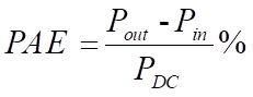
In an ideal PA, PAE=1. This means that the power delivered to the load is equal to the power derived from the DC supply, which states that there is no power consumption in the PA. Unfortunately, this can’t happen because there is no fully linear PA.
Figure 3 shows a normal PA input power vs. output power characteristic under ideal linear response conditions with and without DPD. As input power increases, the PA response becomes more nonlinear, eventually reaching a saturation point. This nonlinearity induces in-band and out-of-band distortion on the transmitted signal, reducing link quality. To achieve the desired linearity, the PA must operate in the linear region, which means the PA needs a lower input power.
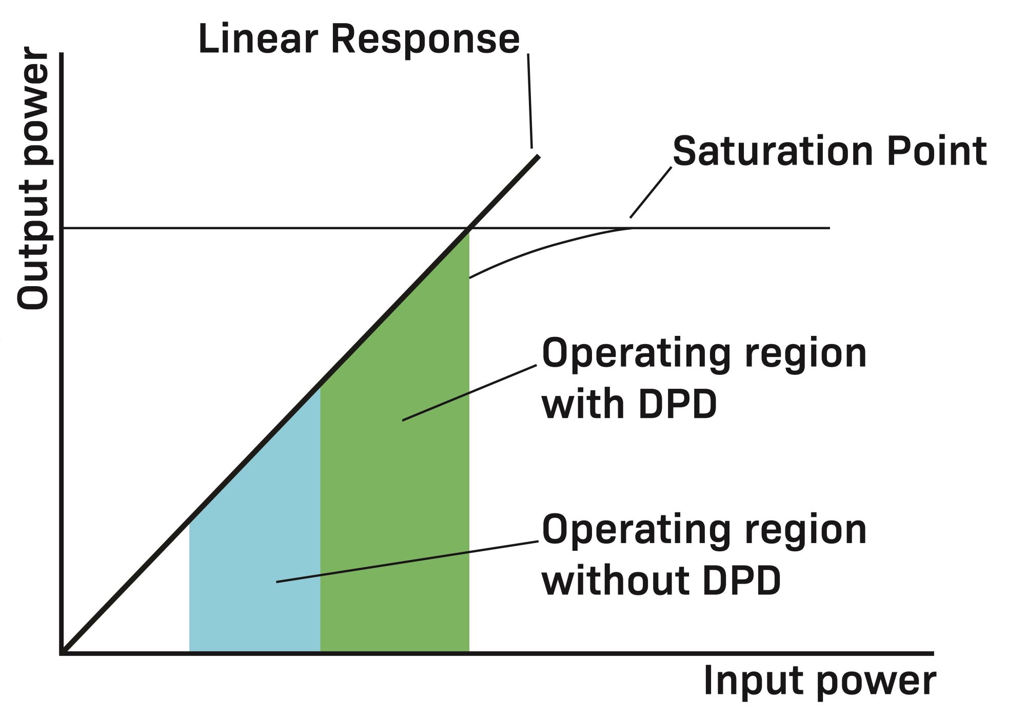
Figure 3. DPD moves a PA’s operating region closer to its saturation point.
The degree of the back-off is normally described relative to the 3 dB saturation point (PSAT(3 dB)) is the point where the PA output power is 3 dB less than it would be if the PA characteristic were perfectly linear. The blue area in Fig. 3 shows a PA’s operating region without DPD, with input power backed off to maintain linearity. For a typical power amplifier, drain efficiency increases with input power so operating in a backed-off state translates to poor power efficiency. One approach to improve efficiency in this scenario is to use a much higher spec PA, but this has significant cost implications. By adding DPD to the system, the PA can operate at higher output power levels while still meeting spectral emission mask requirements. This DPD-enabled operating region is shown in green in Fig. 3 and results in an improvement in the device PAE.
Despite the attractive benefits of DPD, there are still some factors that limit the maximum power at which the PA can operate. For example, we must account for the PAPR of the input signal – with a high PAPR signal requiring the PA to operate further from the saturation point, reducing the power efficiency.
DPD Challenges in 5G Systems
Modern 5G systems present several challenges for DPD implementation, which include:
- Wide bandwidth. To meet the promise of drastically increased upload and download speeds, 5G systems must support wider bandwidth signals than previous generations. In a 5G system, the instantaneous bandwidth (IBW) can be as high as 400 MHz. For DPD, the challenge of increased signal bandwidth is two-fold. Firstly, PA’s exhibit increased memory effects with wideband signals and require more complex modelling techniques to characterize and compensate. Secondly, the feedback path in the DPD model adaptation chain must be improved to capture a signal of sufficient quality to extract a suitable DPD model. In general, DPD adaption requires that the feedback path sampling rate be high enough to capture five times the signal bandwidth – meaning increased cost and implementation complexity as bandwidth increases.
- Multi-band and multi-carrier. Another challenge facing DPD is in the multi-carrier applications (inter-band or intra-band). Here, the main issues are the separate DPD processing needed for each band and the high PAPR signal.
- Massive MIMO (mMIMO). With mMIMO, the main challenge is the large number of PAs that the DPD algorithm should be able to track and linearize the behavioral changes of each PA. Depending on the system size, this can drastically increase the processing requirements and the power consumption.
- Time division duplex (TDD) operation. The main challenge associated with TDD operation comes from the PA switching on and off in a duty cycle. The DPD must model the thermal effects of the transistor and PA characteristics during this switching.
Conclusion
DPD is one of the main blocks in the digital front-end of communication systems. It increases the power efficiency of the system by linearizing the PA. Without DPD, the PA must operate with large back-off to meet the spectral emission mask which then reduces the output power and the overall power efficiency. To achieve the desired output power, a much higher spec PA is needed. This significantly increases the system cost. DPD provides a cost-effective solution to achieve the expected output power, while also meeting spectral emission requirements.
 Pooria Varahram is Research and Development Principal Engineer at Benetel. He has previously held positions at Ericsson and Maynooth University. He holds a PhD in wireless communication systems from University of Putra Malaysia.