• Skip to primary navigation
  • Skip to main content
  • Skip to primary sidebar
  • Skip to footer

Microcontroller Tips

Microcontroller engineering resources, new microcontroller products and electronics engineering news

  • Products
    • 8-bit
    • 16-bit
    • 32-bit
    • 64-bit
  • Applications
    • Automotive
    • Connectivity
    • Consumer Electronics
    • Industrial
    • Medical
    • Security
  • EE Forums
    • EDABoard.com
    • Electro-Tech-Online.com
  • Videos
    • TI Microcontroller Videos
  • EE Resources
    • DesignFast
    • eBooks / Tech Tips
    • FAQs
    • LEAP Awards
    • Podcasts
    • Webinars
    • White Papers
  • EE Learning Center
    • Design Guides
      • WiFi & the IOT Design Guide
      • Microcontrollers Design Guide
      • State of the Art Inductors Design Guide
      • Power Electronics & Programmable Power

Designing a Microprocessor from Scratch

November 4, 2014 By Aimee Kalnoskas

By Val Gretchev, Electro-Tech-Online member

Many students in Electrical Engineering learn how to use and program a microprocessor but very few know what goes on inside. This article will give the reader insight into the inner workings of a very simple microprocessor that can be extended to more powerful designs. I will use a visual method of ANDs, ORs, and Inverters to implement the data paths and controls. In order to do that, we have to use a logic simulator to test the design. Fortunately, there is a simple free program (CEDAR Logic) that accomplishes this task and is easy to learn. You can download the CEDAR Logic Simulator here.

Before integrated microprocessors, there was a wonderful chip with a number designation of 74181 (a 4-bit ALU). This was a time when you made up a microprocessor using many TTL logic chips. Two or four of these ALU chips made the core of a microprocessor. For a 16-bit ALU, there was a companion chip designated 74182 which was used to speed up the carry output. These chips are no longer readily available but the published circuit diagram makes it useful for simulation. You can view datasheets here: DM74LS181 REFERENCE_MANUAL-HCS08, SN74LS182, SN74LS182DM74LS181.

Design Description
The block diagram below shows the data paths that feed the ALU and RAM.

datapath


There is only 1 Accumulator for simplicity. Control logic is centered on a 32-bit ROM that implements the sequences for fetching data from RAM and decoding the instructions. You can view the sequences as a state diagram but traditionally it’s called horizontal programming as shown here.

picoCode

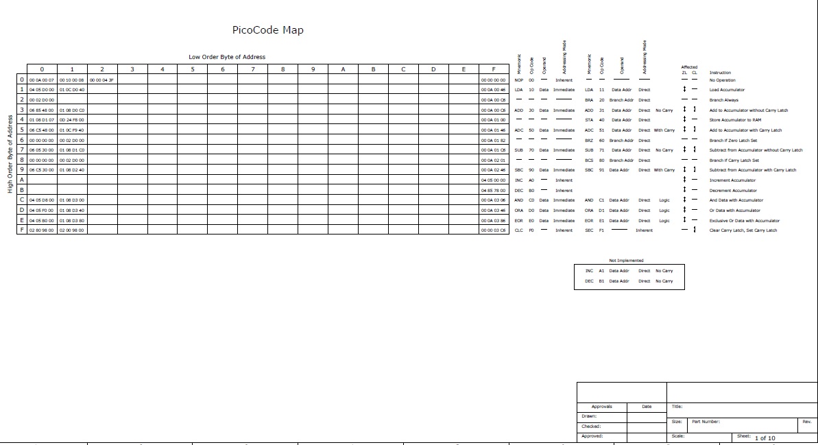
Each program word is 32 bits wide and includes the next address of the flow. Two way branching is possible on the Carry Latch, Zero Latch and bit 0 of the Op Code Register. A 16 way branch can be performed on the high-order 4 bits of the Op Code Register.

As mentioned before, the Arithmetic-Logic-Unit is based on the 74181 datasheet. Refer to image below of the circuit as presented by the simulator.

ALU

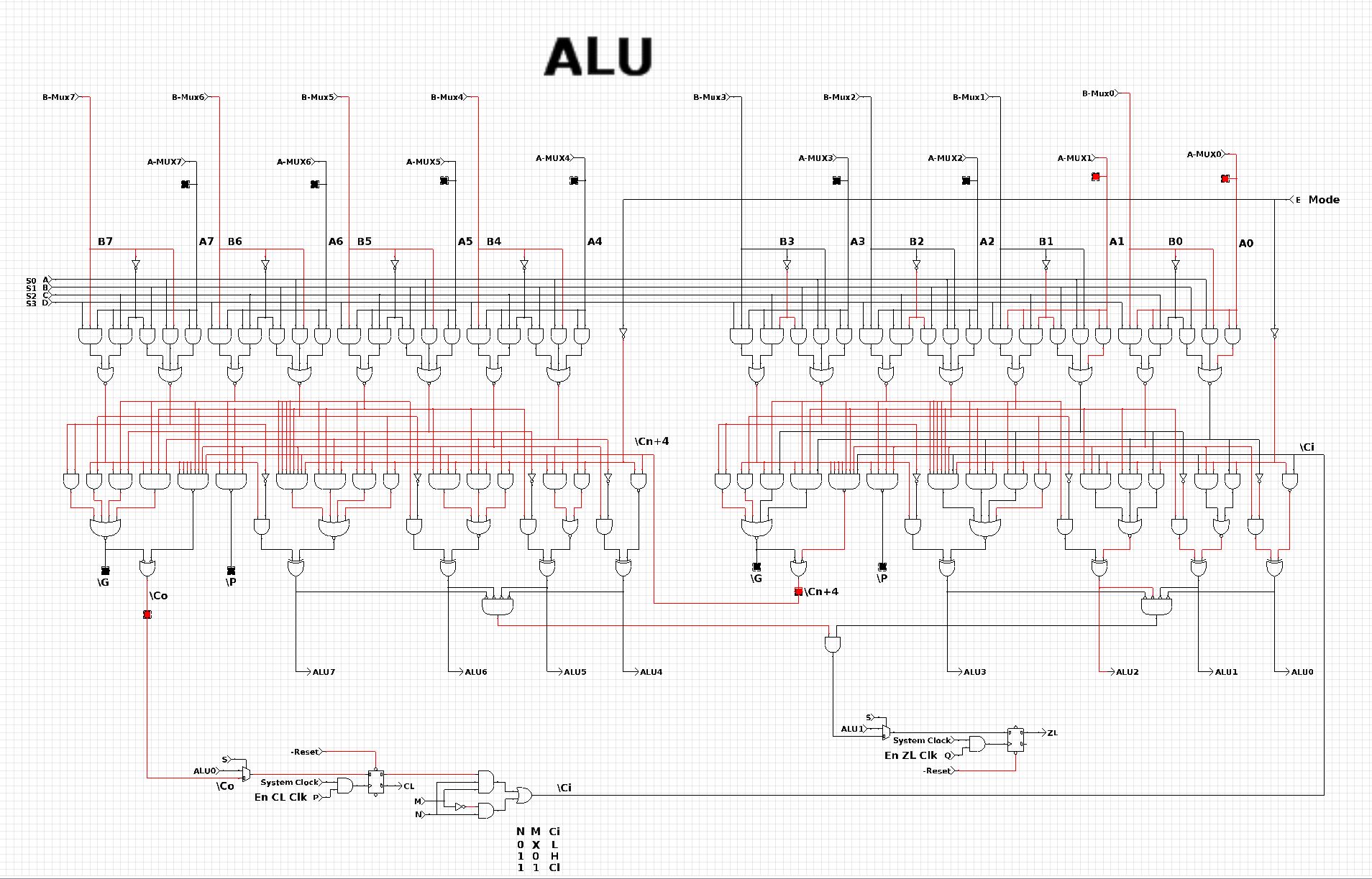
This shows the data paths feeding the A-side of the ALU…

A-SidePath


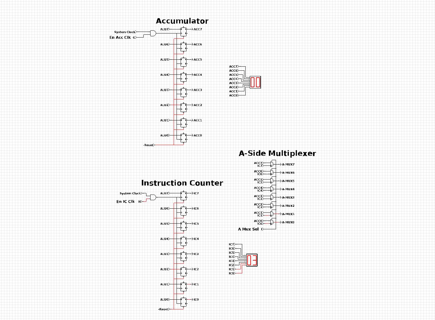
…and this shows the B-side data path for the ALU:

SystemRAM


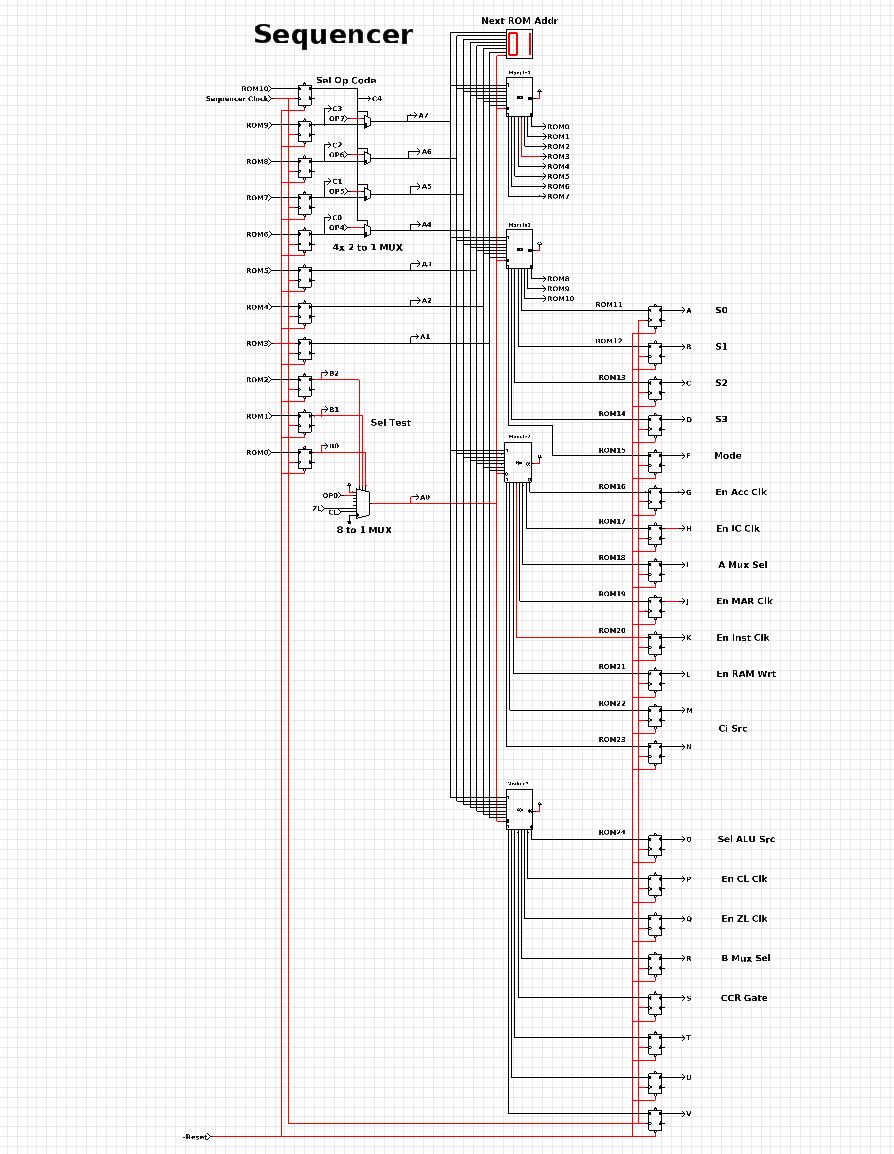
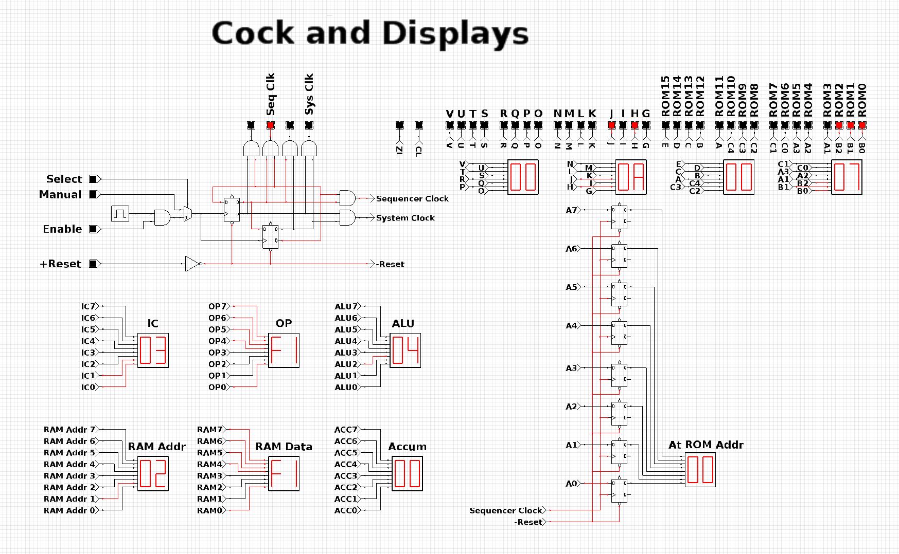
And the sequencer and clock and displays complete the entire design.

SequencerClockAndDisplay


Additional Documentation

Description REFERENCE_MANUAL-HCS08

Description (includes Instruction Sets)


Filed Under: Products Tagged With: electro-tech-online, microprocessor

Primary Sidebar

DesignFast

Design Fast Logo
Component Selection Made Simple.

Try it Today
design fast globle

EE Training Center Classrooms

EE Classrooms

CURRENT DIGITAL ISSUE

A frequency you can count on There are few constants in life, but what few there are might include death, taxes, and a U.S. grid frequency that doesn’t vary by more than ±0.5 Hz. However, the certainty of the grid frequency is coming into question, thanks to the rising percentage of renewable energy sources that…

Digital Edition Back Issues

Subscribe to our Newsletter

Subscribe to weekly industry news, new product innovations and more.

Subscribe today

RSS Current EDABoard.com discussions

  • Regarding Induction Heating From Low Voltage DC
  • [moved] Question to Forum moderators - When to start new thread
  • Help designing 1.6KW Isolated AC/DC with Constant Current Output
  • Variable Frequency and Amplitude Oscillator Circuit
  • Reducing switching noise in MOSFET inverter

RSS Current Electro-Tech-Online.com Discussions

  • Light Automation via mqtt
  • uc3843 Buck-boost
  • How to power up two stereo audio amplifiers from a single source of power supply
  • Nokia 5110 HW in Oshonsoft
  • Drill speed controller fault

Footer

Microcontroller Tips

EE World Online Network

  • DesignFast
  • EE World Online
  • EDA Board Forums
  • Electro Tech Online Forums
  • Connector Tips
  • Analog IC Tips
  • Power Electronic Tips
  • Sensor Tips
  • Test and Measurement Tips
  • Wire and Cable Tips
  • 5G Technology World

Microcontroller Tips

  • Subscribe to our newsletter
  • Advertise with us
  • Contact us
  • About us
Follow us on Twitter Add us on Facebook Follow us on YouTube  Follow us on Instagram

Copyright © 2022 · WTWH Media LLC and its licensors. All rights reserved.
The material on this site may not be reproduced, distributed, transmitted, cached or otherwise used, except with the prior written permission of WTWH Media.

Privacy Policy