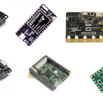
Power consumption of the embedded controller is a primary concern in low-power design. Arduino boards are often used in devices that rely on battery or solar charging. Such devices often deploy far from the power line to have periodic battery replacement or are mobile devices designed for periodic charging cycles. In such a case, optimizing Arduino for low power consumption is essential. Optimizing Arduino also makes it possible to ensure that the entire circuit is utilized most efficiently. Several measures can be applied to reduce the overall power consumption of the controller. The net power consumption by the device, however, still depends upon other components interfaced with the controller.
There are several hacks and tricks that designers use to reduce the power consumption of the Arduino board. When a low-power design is a priority, designers first choose an Arduino board with a lower operational voltage. An Arduino board selection cannot be solely based on operating voltage or power consumption. Often, a low-power Arduino may not fit well to a particular application. Usually, low-power variants have fewer hardware features or fewer GPIO. In such situations, the application may not be feasible or may get compromised using a low-power Arduino. Irrespective of the Arduino board selected for a given application, designers almost always use Arduino sleep modes or power save modes to optimize power consumption.
Apart from selecting a low-power Arduino and using power save modes, some software and hardware hacks can be used to reduce power consumption. The software hacks include reducing clock speed, lowering operation voltage, and optimizing software code for low power. One should take care that software hacks do not compromise the intended performance of the application. The hardware hack includes removing extra hardware from the Arduino board that may not be utilized after deploying the application/device. Let us discuss all these power-saving measures for Arduino.
Selecting the right Arduino
First, the smallest Arduino board that fits the bill must be selected for a low power design. If an application does not have many external components, Arduino nano or Arduino Pro Mini should be used instead of Arduino UNO or MEGA. Typically, Arduino Nano has a power consumption of 20-30 mA when powered by a 9V battery. In the same application, Arduino Pro Mini may have a power consumption of 15-20 mA. The Arduino Pro Mini 3V3 has a power consumption of less than 10mA. If an application requires more GPIO or many microcontroller features, then only Arduino UNO or MEGA should be selected.
Interestingly, Arduino MEGA does have more GPIO and built-in peripherals; its power consumption is less by one-third compared to Arduino UNO. The power footprint of Arduino UNO typically goes 100-120 mA, while the MEGA may only consume anywhere between 70-80 mA for the same application. Note that the power footprint of a Nano is one-fifth of an Arduino and one-fourth of a Mega. Using 3V3 Pro Mini may further reduce the power consumption by 50 percent.
Arduino low-power modes
The best way to reduce the power consumption of a battery-powered application is using power-save modes. Each microcontroller has sleep modes or power-save modes. Most of the Arduino boards are based on the ATmega328P controller, which provides six power save modes. These are also called sleep modes or standby modes. These modes can be activated with the help of the LowPower.h library. The power.h or sleep.h libraries can also manage Arduino sleep modes. The six power save modes in Arduino are:
- Idle mode
- ADC noise reduction mode
- Power-down mode
- Power-save mode
- Standby mode
- Extended standby mode
For activating any of the above sleep modes, the Sleep Enable (SE) bit in the Sleep Mode Control Register (SMCR) must be set to 1. A particular sleep mode can be selected by setting Sleep Mode Select bits (SMCR.SM[2:0]). Once sleep mode is activated and one of the modes is selected, the sleep mode can be executed by calling SLEEP instruction. For waking up Arduino from sleep mode, a reset button can be pressed, or an Arduino interrupt can be programmed. During sleep modes, the power consumption of Arduino boards is reduced to a few micro-ampere compared to power consumption in several milli-ampere in an active state.
Arduino idle mode
The idle mode is activated by writing ‘000’ to the Sleep Mode Select bits (SMCR.SM[2:0]). In idle mode, the clock signal for both CPU and flash is disabled while the clock signal for other peripherals is kept live. Therefore, the CPU is shut down while USART, SPI, TWI, timer/counter, analog comparator, watchdog timer, and interrupts remain operational. Software or external interrupt can be used to wake up Arduino from idle sleep mode. The software interrupt can be timer overflow or USART. A push button or sensor can generate the external interrupt. The Arduino can also be waked up from idle mode using a time delay.
LowPower.h must be imported into the Arduino sketch for activating idle mode. The library can be found at the following link. The library needs to be downloaded as a ZIP file and included in Arduino libraries by navigating Sketch -> Include Library -> Add .Zip Library in the Arduino IDE. The library can be imported in Arduino sketch using:
#include “LowPower.h”
To activate idle mode in ATmega328P/ATmega168-based Arduino, add the following statement to the loop() function:
LowPower.idle(SLEEP_8S, ADC_OFF, TIMER2_OFF, TIMER1_OFF, TIMER0_OFF, SPI_OFF, USART0_OFF, TWI_OFF);
The above statement activates the idle mode for 8 seconds. The Idle mode can be activated for 15ms, 30ms, 60ms, 120ms, 250ms, 500ms, 1 second, 2 second, 4 second, 8 seconds or forever by passing SLEEP_15MS, SLEEP_30MS, SLEEP_60MS, SLEEP_120MS, SLEEP_250MS, SLEEP_500MS, SLEEP_1S, SLEEP_2S, SLEEP_4S, SLEEP_8S or SLEEP_FOREVER as argument respectively. The above statement also turns off the analog comparator, timer 0, timer 1, timer 2, USART, TWI, and SPI.
To activate idle mode in ATmega32U4-based Arduino, add the following statement to the loop() function:
LowPower.idle(SLEEP_8S, ADC_OFF, TIMER4_OFF, TIMER3_OFF, TIMER1_OFF, TIMER0_OFF, SPI_OFF, USART1_OFF, TWI_OFF, USB_OFF);
To activate idle mode in ATmega2560-based Arduino, add the following statement to the loop() function:
LowPower.idle(SLEEP_8S, ADC_OFF, TIMER5_OFF, TIMER4_OFF, TIMER3_OFF, TIMER2_OFF, TIMER1_OFF, TIMER0_OFF, SPI_OFF, USART3_OFF, USART2_OFF, USART1_OFF, USART0_OFF, TWI_OFF);
To activate idle mode in ATmega256RFR2-based Arduino, add the following statement to the loop() function:
LowPower.idle(SLEEP_8S, ADC_OFF, TIMER5_OFF, TIMER4_OFF, TIMER3_OFF, TIMER2_OFF, TIMER1_OFF, TIMER0_OFF, SPI_OFF, USART1_OFF, USART0_OFF, TWI_OFF);
The analog comparator can be switched OFF or kept ON using ADC_OFF or ADC_ON as an argument, respectively. The timer 0 can be switched OFF or kept ON using TIMER0_OFF or TIMER0_ON as an argument, respectively.
Similarly, Timer 1, Timer 2, Timer 3, Timer 4, and Timer 5 are switched OFF/ON using TIMER1_OFF/TIMER1_ON, TIMER2_OFF/TIMER2_ON, TIMER3_OFF/TIMER3_ON, TIMER4_OFF/TIMER4_ON, and TIMER5_OFF/TIMER5_ON as argument respectively. The USART 0, USART 1, USART 2 and USART 3 can be turned OFF or kept ON using USART0_OFF/USART0_ON, USART1_OFF/USART1_ON, USART2_OFF/USART2_ON and USART3_OFF/USART3_ON as argument respectively.
The TWI can be switched OFF or kept ON using TWI_OFF or TWI_ON as an argument, respectively. The SPI can be switched OFF or kept ON using SPI_OFF or SPI_ON as an argument, respectively. The USB port can be switched OFF or kept ON using USB_OFF or USB_ON as an argument.
The ATmega328P-based Arduino like Nano, Pro Mini, and UNO have a Brown-out Detector (BOD) to monitor power supply voltage during the sleep modes. The BOD can be turned OFF or kept ON using BOD_OFF or BOD_ON as an argument, respectively. The maximum preset duration for the Idle sleep mode is 8 seconds. The duration can be increased by calling the LowPower.idle() within a loop. For example, the following statement puts Arduino in an idle sleep of 40 seconds:
for(int i = 0; i<= 4; i++)
{
LowPower.idle(SLEEP_8S, ADC_OFF, TIMER2_OFF, TIMER1_OFF, TIMER0_OFF,SPI_OFF, USART0_OFF, TWI_OFF);
}
Using for loop to increase sleep duration is quite useful. For example, Arduino can be put to sleep for several minutes, then wake up for a few seconds to take sensor readings or perform other application tasks.
Arduino ADC noise reduction mode
The ADC noise reduction sleep mode is activated by setting ‘001’ to the Sleep Mode Select bits (SMCR.SM[2:0]). In this mode, the clock signal for CPU, flash, and input/output are stopped while the clock signal for other peripherals remains live. The analog comparator, timer/counter, watchdog timer, TWI, and external interrupts remain active in the ADC noise reduction mode.
The Arduino can wake up using an external reset, an external level interrupt on INT, pin change interrupt, timer interrupt, SPM/EEPROM ready interrupt, brown-out reset, watchdog interrupt, watchdog system reset, or TWI address match.
Again LowPower.h can be used for activating ADC noise reduction mode. Add the following line to activate this sleep mode in the loop() function:
LowPower.adcNoiseReduction(SLEEP_8S, ADC_OFF, TIMER2_OFF)
Note that LowPower.h let switching off analog comparator and timer two explicitly for ADC noise reduction mode. The sleep mode can be activated for 15ms, 30ms, 60ms, 120ms, 250ms, 500ms, 1 second, 2 seconds, 4 seconds, 8 seconds, or forever.
Arduino power-down mode
The power-down mode can be activated by writing ‘010’ to the Sleep Mode Select bits (SMCR.SM[2:0]). All generated clocks are stopped in this mode while asynchronous modules remain active. Therefore, only external interrupts, TWI address match, and watchdog timer remain operational.
Arduino can wake up from power-down mode using external reset, external interrupt on INT pin, pin change interrupt, watchdog interrupt, watchdog system reset, TWI address match, or Brow-out reset.
Again, LowPower.h can be used to activate the power-down mode. Add the following statement to activate this sleep mode in the loop() function:
LowPower.powerDown(SLEEP_FOREVER, ADC_OFF, BOD_OFF);
Note that BOD and analog comparator can be explicitly turned OFF or kept ON for power down mode. The sleep mode can be activated for 15ms, 30ms, 60ms, 120ms, 250ms, 500ms, 1 second, 2 seconds, 4 seconds, 8 seconds, or forever.
The following is a valid example of waking up Arduino from power down mode using an external interrupt:
#include “LowPower.h”
const int wakeUpPin = 2;
void wakeUp(){#interrupt_handler}
void setup(){ pinMode(wakeUpPin, INPUT);}
void loop()
{
attachInterrupt(0, wakeUp, LOW);
LowPower.powerDown(SLEEP_FOREVER, ADC_OFF, BOD_OFF);
detachInterrupt(0);
}
The following is a valid example of waking up Arduino periodically from power-down mode.
#include “LowPower.h”
void setup(){}
void loop()
{
LowPower.powerDown(SLEEP_8S, ADC_OFF, BOD_OFF);
}
Arduino power-save mode
The power-save mode is activated by writing ‘011’ to the Sleep Mode Select bits (SMCR.SM[2:0]). This mode is the same as power-down mode, except that Timer 2 is enabled. Therefore, timer overflow and output compare events can be used to wake up the Arduino.
Again, LowPower.h can be used to activate the power-save mode. Add the following statement to activate this sleep mode in the loop() function:
LowPower.powerSave(SLEEP_8S, ADC_OFF, BOD_OFF, TIMER2_OFF)
Note that LowPower.h let explicitly turn ON/OFF analog comparator, Brown-out Detector, and Timer 2. The sleep mode can be activated for 15ms, 30ms, 60ms, 120ms, 250ms, 500ms, 1 second, 2 seconds, 4 seconds, 8 seconds, or forever.
Arduino standby mode
The standby mode is activated by writing ‘110’ to the Sleep Mode Select bits (SMCR.SM[2:0]). This mode is the same as power-down mode, except that the external oscillator keeps running in this mode.
Again, LowPower.h can be used to activate standby mode. Add the following statement to activate this sleep mode in the loop() function:
LowPower.powerStandby(SLEEP_8S, ADC_OFF, BOD_OFF)
Note that LowPower.h let turn off analog comparator and brown-out detector explicitly for this mode. The sleep mode can be activated for 15ms, 30ms, 60ms, 120ms, 250ms, 500ms, 1 second, 2 seconds, 4 seconds, 8 seconds, or forever. Note that LowPower.h offer only idle and standby sleep modes for SAMD21G18A-based Arduino boards.
Arduino extended standby mode
The extended standby mode is activated by writing ‘111’ to the Sleep Mode Select bits (SMCR.SM[2:0]). This mode is the same as power-save mode, except that the external oscillator keeps running in this mode.
Again, LowPower.h can be used to activate extended standby mode. Add the following statement to activate this sleep mode in the loop() function:
LowPower.powerExtStandby(SLEEP_8S, ADC_OFF, BOD_OFF, TIMER2_OFF)
Note that LowPower.h let switching OFF analog comparator, brown-out detector, and Timer 2 explicitly for this mode. The sleep mode can be activated for 15ms, 30ms, 60ms, 120ms, 250ms, 500ms, 1 second, 2 seconds, 4 seconds, 8 seconds, or forever. The extended standby mode takes five clock cycles to wake up.
Reducing clock speed
If timing is not important in an embedded application or the application does not require the execution of many instructions, the clock speed can be reduced to save battery life. It can triple the battery life by reducing the clock speed by half. The clock speed determines the number of instructions Arduino can execute per second. If the clock frequency is 16MHz, Arduino can perform 16 million instructions per second. Table 1 lists the default clock frequency for different Arduino boards.

Note that reducing the clock frequency also increases the execution time of the Arduino sketch. For example, if an Arduino sketch takes five seconds to execute with a 16 MHz frequency, it will take ten seconds to execute with a clock frequency of 8 MHz. This may reduce the actual sleep time of the Arduino. Reducing the clock frequency also affects the operation of synchronous peripherals like ADC, flash, and Input/Output.

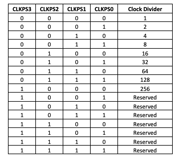
To reduce clock speed, a system clock Pre-scaler is used. The clock Pre-scaler is controlled by Arduino’s Clock Pre-scale Register (CLKPR). The register has the bit diagram shown in Table 2.
First, the clock Pre-scaler must be activated by setting the CLKPCE bit to 1. Then, the clock divider can be selected by setting CLKPS3, CLKPS2, CLKPS1, and CLKPS0 bits according to Table 3.
To reduce the clock speed by half, add the following lines in the setup() function.
CLKPR = 0x80; // Enable clock prescale
CLKPR = 0x01; // Use clock division factor 2
The power consumption can be reduced by reducing the clock speed from 20% to 60%. Each Arduino board has a different response for reducing the clock frequency.
Lowering operation voltage
By lowering the supply voltage, the power consumption can be reduced by more than half. However, lowering supply voltage must accompany lowering clock speed as Arduino may behave strangely if it is clocked at default frequency while the operating voltage is reduced. Arduino boards may also have a certain maximum clock frequency for lower voltages. For example, if ATmega328P-based Arduino is operated at 3.3V, i.e., their minimum operational voltage, the maximum clock speed should be 13 MHz in contrast to the default of 16 MHz. The operation voltage and clock speed are related according to Figure 1.
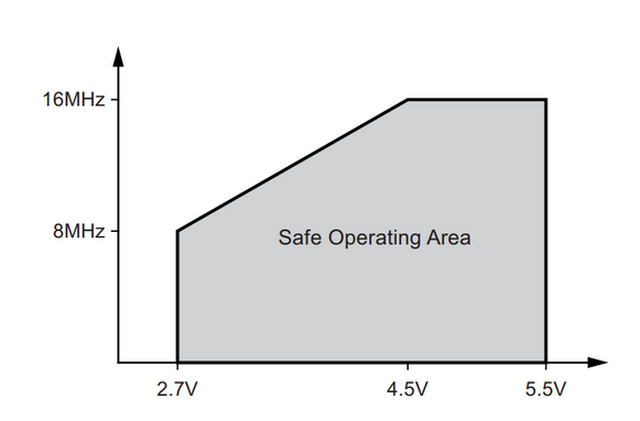
The operation voltage and clock speed are also related according to Figure 2.
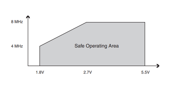
Table 4 lists the possible minimum supply voltage with reduced clock speeds for different Arduino boards.

Reducing the operation voltage can save power consumption by 15-20 percent. The reduction of operation voltage also extends the time battery is reached the minimum supply voltage for the Arduino. This way, the battery replacement may be required over a longer period than Arduino operating at typical operation voltage.
Optimizing Arduino sketch
To further reduce the power consumption of Arduino, the built-in peripherals can be explicitly turned OFF within the sketch. The built-in peripherals like timer/counter, watchdog timer, brown-out detector, and analog comparator keep consuming power irrespective of whether they are utilized or not by the Arduino program. When implementing sleep modes using LowPower.h library, appropriate built-in peripherals can be explicitly turned OFF by passing their respective arguments. If a built-in peripheral like ADC or timer/counter is required, it can be activated by writing its corresponding registers, then again deactivated. This is a nice trick to optimize power consumption with the help of Arduino software.
Removing unused components
On an Arduino board, not just the SoC, other components on the PCB also draw current that contributes to the net power consumption from the battery. The USB bridge on the Arduino boards alone consumes around 10mA. After uploading the final Arduino sketch, the USB bridge can be removed from the Arduino PCB to reduce some power consumption. However, this can be done only if the Arduino board does not need to be reprogrammed anytime.
Similarly, the onboard voltage regulator also wastes a lot of battery power as the power is drained due to the difference between the voltage drawn by the ATmega328 and the actual voltage supplied by the battery. The onboard voltage regulator can be removed, and Arduino can be powered by an SMPS instead. The onboard linear regulator has a power efficiency of around 70 percent, which is far less than the typical 90 percent efficiency of SMPS. Adding SMPS will add some additional cost to the embedded device.
Conclusion
Low power design is a significant concern in battery-powered embedded devices. The Arduino can be optimized for low-power applications by choosing a low-power Arduino, using power-save modes, reducing clock speed, lowering operation voltage, disabling used peripherals in the Arduino sketch, and removing extra components from the Arduino PCB.


