Adding simple RFID tags to hospitals’ widely used pneumatic-tube systems has dramatically improved performance without needing a system rebuild.
Wireless solves the problem — and does more
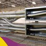
Modern electronic technology has reinvigorated the pneumatic tube system to do more and do better without requiring more tube pathways. This can apply to upgrading an existing installed system or a “from scratch” system going into a newly built facility with cost and space constraints. That’s especially important as hospitals are severe in-wall and between-floor space cornetists. They must contain PTS tubing, oxygen piping, vacuum piping, special drainage, and much more besides relatively thin coaxial, optical fiber, and Ethernet cabling).
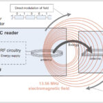
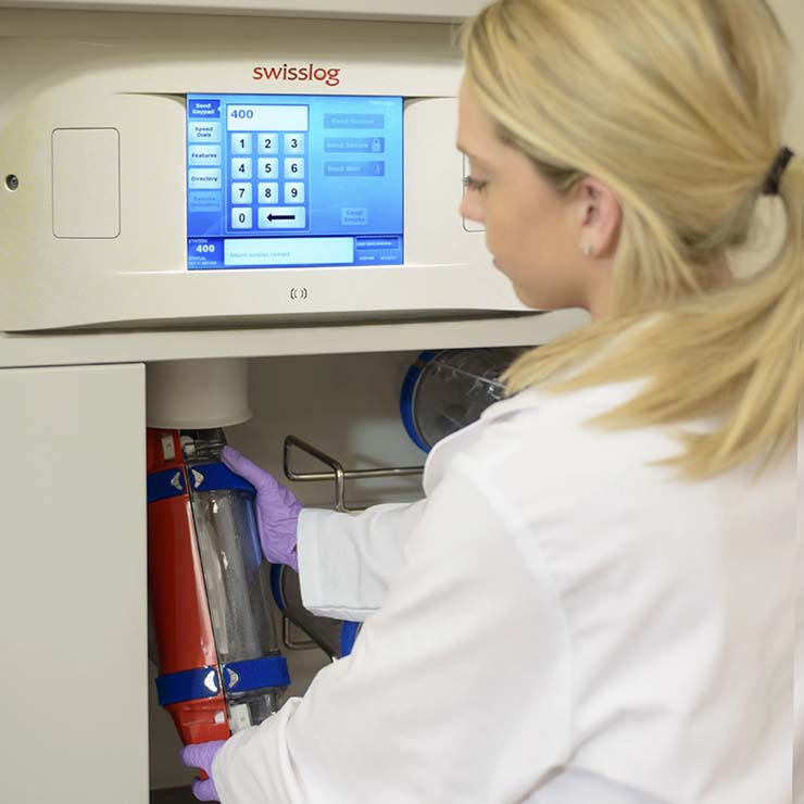
In addition to paper labels indicating the destination address (needed for personal convenience and backup) or bar-code slips to be inserted into the carrier, these newest systems use RFID technology to label each carrier (Figure 1). The user at the sending station enters the address code on the touchscreen keypad, and the tube-management system writes that address code into a re-writeable RFID tag permanently attached to that carrier.
From that point on, the system is totally automated. As the carriers speed between 15 and 20 mph (20 to 30 km/hr), they are continuously tracked and routed via transfer units (switching nodes called diverters) onto the best available path to the recipient. These advanced systems feature adjustable transport velocity so that blood samples, for example, can be transported gently at a reduced speed.
The system management does more than just direct each carrier on its journey. It checks that it is going where it should be going (problems do occur, but rarely), identifies traffic jams due to a stuck carrier (again, surprisingly rare), continuously monitors and manages traffic flow, waits, and queue sizes, and even ensures that enough empty carriers are returned to each sending station based on use patterns. Many systems even have a provision for rushing critical items such as blood to an operating room via a “priority” carrier coding, allowing these carriers to supersede other ones in the routing plan and travel path.
These systems are complicated networks and have many parallels to electronic communication systems. The system at Stanford University Hospital has 124 stations (every nursing unit has its own); 141 transfer units (diverters), 99 inter-zone connectors, and 29 blowers. Maximum travel time for a carrier over the many thousands of feet between sender and receiver is under three minutes in most cases, even during peak traffic.
The analysis of traffic, waits, queues, and other parameters is as quantitative as it is for many electronic networks. A pneumatic tube system is a good example of a queuing system with a finite capacity to deliver, and the demand placed on it is random and variable. A large system can be handling hundreds of these carriers per hour, which doesn’t sound like much until you realize that average travel time and wait for arrival is not the key parameter; maximum wait (delay) is what counts in this setting.
As such, it can be analyzed by all the classic statistical techniques used for assessing queuing and traffic flow (erlangs was the key figure for telephone systems). Of course, PTS speed and capacity are much lower than in vehicular traffic, an electronic network, or most other appearances of such queuing — but the analysis principles are the same.
As with all queuing models and their analysis, performance will be relatively unaffected by the traffic load specifics when that number is low, then starts to deteriorate modestly with an increase in traffic, eventually reaching an inflection point where the delays increase dramatically. The specifics depend on the incoming traffic rate (average and peak), system structure and capacity, and other system parameters, all of which are entered into the statistical model.
For example, in representative system configuration (Figure 2, left), almost all “sends” will be in a queue of four or fewer until system loadings go beyond 50%. Still, beyond 50%, the proportion of carriers in this relatively short queue reduces sharply. If the graph is reversed (Figure 2, right) to show carriers queuing longer than four, the graph turns steeply upwards beyond approximately 60% loading.
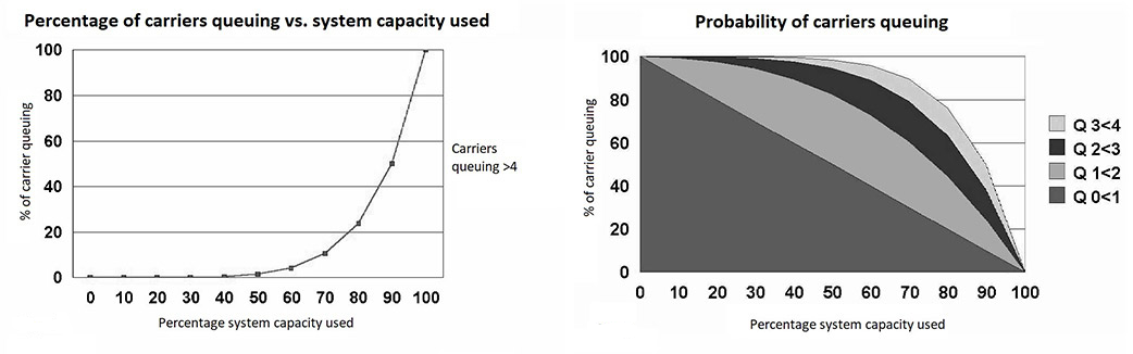
The 60% threshold can therefore be considered a target capacity loading when designing a PTS network if the aim is to move the majority of carriers promptly. It can also be seen that designing a network where the predicted traffic occupies less than around 30% of the available capacity is excessive and a waste of resources unless high growth rates are forecast. Further, the software dynamically optimizes routing to achieve the fastest transaction times, even during peak usage.
This is especially useful as the traffic sources (where the carriers come from) are widely spread out, as are the receiving stations, and no signal station usually generates more than a few carriers in any reasonable period. This is very different than many communications networks where a lot of the traffic comes from an individual node or there is a large volume of continuous traffic, such as when downloading a streaming event or show.
Conclusion
Even without the upgrade and benefits of RFID tags, these pneumatic-tube systems were in no danger of being obsolete, as there is no viable alternative to their function (that is until Star Trek-like transporters and replicators become available). Given that reality, it’s interesting to see how adding RFID tags to the carriers in these systems has built a management superstructure that has improved system performance, throughput, reliability, and other critical specifications, even as the system load factor has increased. While this is not an IoT success story in the formal sense, as the tags do not use the Internet, it is a wireless and RFID success story.
Related EE World content
Driverless Vehicles May Lead to Traffic Congestion in Cities
Analyst: 5G is all about the traffic
Adaptive Cruise Control Vehicles Create Phantom Traffic Jams in Road Test
New Smart System to Reduce Queues at Roundabouts
External References
Pneumatic Tubes for Hospitals
- Swisslog Healthcare, “TransLogic® Pneumatic Tube Systems”
- HCO News, “Pneumatic Tube Systems Help Deliver Better Patient Care”
- Wired, “Hospitals Still Use Pneumatic Tubes—and They Can Be Hacked”
- Penn Medicine News, “HUP’s P-Tube System: Keeping Services Up and Running”
- Air-Log International, “Pneumatic Tube Systems in hospitals”
- University of Iowa Medical Center, “Hidden health care: Guardians of the pneumatic tube system”
- Telecom Pneumatic Tube Systems, “Design issues in creating efficient Pneumatic Tube Transport networks”
- Stanford University, “Gone with the wind: Tubes are whisking samples across hospital”
- Wikipedia, “Pneumatic tube”
- Explain that Stuff, “Pneumatic tube transport”
Pneumatic Tubes for Postal Mail
- Untapped New York, “The Pneumatic Tube Mail System in New York City”
- United States Postal Service, “The Pneumatic Mail Tubes: New York’s Hidden Highway And Its Development”