• Skip to primary navigation
  • Skip to main content
  • Skip to primary sidebar
  • Skip to footer

Microcontroller Tips

Microcontroller engineering resources, new microcontroller products and electronics engineering news

  • Products
    • 8-bit
    • 16-bit
    • 32-bit
    • 64-bit
  • Applications
    • 5G
    • Automotive
    • Connectivity
    • Consumer Electronics
    • EV Engineering
    • Industrial
    • IoT
    • Medical
    • Security
    • Telecommunications
    • Wearables
    • Wireless
  • Learn
    • eBooks / Tech Tips
    • EE Training Days
    • FAQs
    • Learning Center
    • Tech Toolboxes
    • Webinars/Digital Events
  • Resources
    • Design Guide Library
    • DesignFast
    • LEAP Awards
    • Podcasts
    • White Papers
  • Videos
    • EE Videos & Interviews
    • Teardown Videos
  • EE Forums
    • EDABoard.com
    • Electro-Tech-Online.com
  • Engineering Training Days
  • Advertise
  • Subscribe

Teardown: Amazon 4th generation Echo Dot

December 29, 2022 By Lee Teschler

Echo Dot 
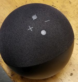
One of the latest incarnations of the Echo Dot boasts premium sound and an ability to pair up with Fire TV devices for a home theater audio experience. Construction-wise, there are usually a few changes from one generation of Echo devices to the next, and sometimes between early and later models of the same generation. With that in mind, we disassembled a 4th generation Echo to analyze the internals.

The teardown begins by removing a rubber foot on the base. Under the rubber cover lies four T5 Torx bolts and a recessed six-pin header which appears to be a debug or programming port. Removing the four Torx bolts reveals a circular light pipe that delivers the LED light to the edge of the base. Beneath the light pipe is the Echo’s first circuit board. The exposed side of

Echo bottom shot
The bottom cover components removed. The white ring is the light guide for the LEDs which reside on the white ring of the circuit board. Click image to enlarge.

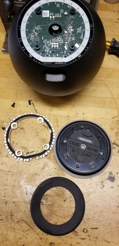
the board holds the 25 LEDs that light up to signal the Echo’s status plus two identical Texas Instruments LED driver chips (LP5036). These each can drive up to 36 LED channels; presumably it takes two of them to produce the multiple colors that the LEDs display.

Flipping the board over reveals two chips protected by metal shields. These turn out to be two identical Texas Instrument class-D audio amps (TAS5805M) capable of driving two speakers. Going

bottom PCB with callouts
Top, the bottom of the audio PCB contains two TI LED drivers plus the LEDs. Below, the other side contains the two audio amps. Click image to enlarge.

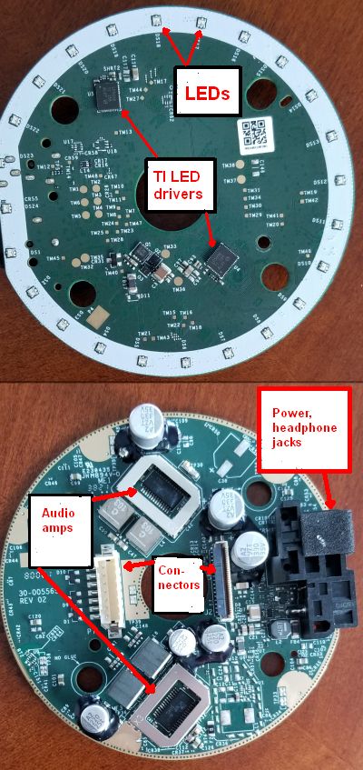
by the application data in the TI datasheet, one handles the big main speaker in the Echo while the other handles the two smaller ones.

Another interesting point about the two ICs is that they both sit beneath metal shields. This sort of shielding is usually reserved for wireless RF modules, but in this case it apparently serves to make a thermal connection to a big die-cast metal piece in the base of the device  separating the audio/LED PCB from the PCB containing the wireless circuits. Besides providing a heat sink for the audio amps, the die-cast piece would also prevent the Echo Dot from being top heavy because of its big speaker and would provide some RFI shielding between the audio board and wireless board as well.

The other component we could identify on the audio amp side of the board was a 30-V P-channel MOSFET (SSFN3903) from Good-Ark Semiconductor in New York.

audio board and housing
The audio board still connected to the housing. Visible here is a thermal connection from the audio amp metal housing to the die cast metal piece. Click image to enlarge

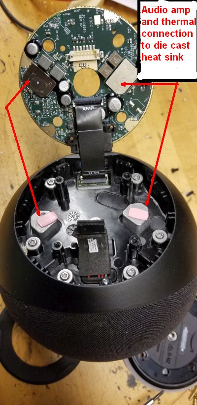
The audio/LED board connects to the wireless board via two flat cables. The wireless board sits on the other side of a die-cast metal piece. It is exposed by first removing the top dome of the Echo, then removing the plastic housing that holds the speakers. This attaches to the plastic housing via Torx screws.

Inside the lower plastic housing is the die-cast metal piece and the PCB holding the RF and processor modules, all shielded with metal cans, plus two flat antennas glued to a separate plastic

top board detail
Top, speakers in place on the plastic housing. Next, the die-cast metal piece. Visible is the thermal tape for heat sinking the voice processor IC. Next, the top of the PCB with antennas in place. Bottom, the other side of the PCB. Click image to enlarge.

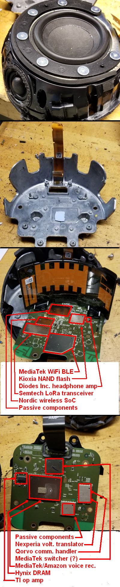
piece. The bottom of the RF PCB contains four metal shielding cans. One sits over a handful of passive components. Beneath another can lies a MediaTek chip designed with Amazon (MT8512) that does the Echo’s speech recognition. In the same can is an SK Hynix 8Gbit SDRAM (H9HCNNN8KUMLHR-NMI). Near the can sits a Texas Instruments very low noise op amp (TL97). In another metal can sits a Nexperia voltage level translator/transceiver (74AVC2T45DP-Q100) and a Qorvo communication controller IC (GP712) that handles in-coming ZigBee communications and provides serial communications to a host processor. The last can on this side holds a MediaTek IC (MT6398AN) which doesn’t seem to be commercially available. Other teardowns have speculated that it is a switching power supply IC.

pushbutton pad
Top, the pushbutton pad mounted in the Echo Dot dome. Below, backing plate removed for a better view of the TI ADCs. Also here but not called out are the microphones. Bottom, the switches and the LEDs that light two of them. Click image to enlarge.
That brings us to the top of the PCB. It includes two connections to the flat antenna structure and five metal cans. One can covers just passive components. It sits next to a can covering a Kioxia 8-GB NAND flash chip (THGBMJG6C1LBAIL). Another can holds a Nordic Semiconductor SoC that handles multiple wireless protocols (nRF52832) via an Arm Cortex-M4 CPU. Next to it sits a Semtech LoRa transceiver (LLCC68), and the last can contains a MediaTek Wifi and Bluetooth module (MT7663BSN). Finally, the stereo headphone amp (PAM8908) from Diodes Inc. also sits on this side of the board.

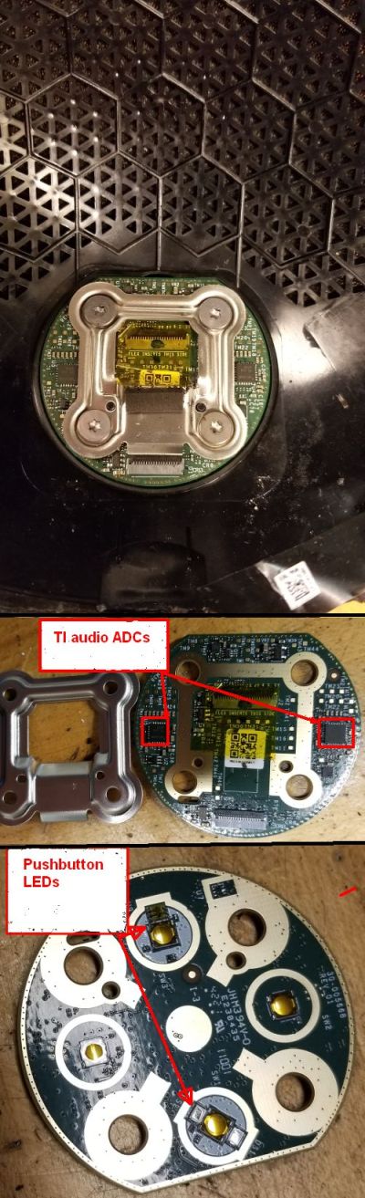
Two flat flex connectors go to the PCB in the dome holding the switches and microphones. Two of the four buttons–the mic able/disable switch and Alexa activation switch–have LEDs that signal actuation. The small switch PCB also contains two identical Texas Instruments audio ADCs (TLV320ADC5140) on its in-facing side each of which will handle four analog microphones.

You may also like:


  • How to turn off a smart meter the hard way
  • router security
    Worst suspicions confirmed: The terrible security of internet routers
  • BLE hacks
    Breaking BLE — Vulnerabilities in pairing protocols leave Bluetooth devices…
  • RF won't hurt you
    No, IoT RF radiation won’t cause a pandemic

Filed Under: Applications, FAQ, Featured, IoT, Teardowns Tagged With: FAQ, mediatek, nordicsemiconductor, qorvo, semtech, texasinstruments

Primary Sidebar

Featured Contributions

Five challenges for developing next-generation ADAS and autonomous vehicles

Securing IoT devices against quantum computing risks

RISC-V implementation strategies for certification of safety-critical systems

What’s new with Matter: how Matter 1.4 is reshaping interoperability and energy management

Edge AI: Revolutionizing real-time data processing and automation

More Featured Contributions

EE TECH TOOLBOX

“ee
Tech Toolbox: Internet of Things
Explore practical strategies for minimizing attack surfaces, managing memory efficiently, and securing firmware. Download now to ensure your IoT implementations remain secure, efficient, and future-ready.

EE Learning Center

EE Learning Center

EE ENGINEERING TRAINING DAYS

engineering
“bills
“microcontroller
EXPAND YOUR KNOWLEDGE AND STAY CONNECTED
Get the latest info on technologies, tools and strategies for EE professionals.

RSS Current EDABoard.com discussions

  • CST Studio – How to increase frequency step size (e.g. to 100 MHz)?
  • What is the difference between MIMO antenna elements arragned radially across the pentagon shaped substrate versus rectangle shaed substrate?
  • General purpose CMOS Op Amp and PMOS & NMOS from LTSpice library
  • Simple Active Bandpass Filter Oscillates
  • TMP117 > Can not read temperature on LCD

RSS Current Electro-Tech-Online.com Discussions

  • Cpu coin acceptor and zero delay arcade board.
  • Capacitive Touch On The Profile
  • JBL charge 4 dead motherboard?
  • Guitar electronics project
  • can a AT89C51 be used as a rom?

DesignFast

Design Fast Logo
Component Selection Made Simple.

Try it Today
design fast globle

Footer

Microcontroller Tips

EE World Online Network

  • 5G Technology World
  • EE World Online
  • Engineers Garage
  • Analog IC Tips
  • Battery Power Tips
  • Connector Tips
  • DesignFast
  • EDA Board Forums
  • Electro Tech Online Forums
  • EV Engineering
  • Power Electronic Tips
  • Sensor Tips
  • Test and Measurement Tips

Microcontroller Tips

  • Subscribe to our newsletter
  • Advertise with us
  • Contact us
  • About us

Copyright © 2025 · WTWH Media LLC and its licensors. All rights reserved.
The material on this site may not be reproduced, distributed, transmitted, cached or otherwise used, except with the prior written permission of WTWH Media.

Privacy Policy