
Power factor measurement using PIC18f4520 – I have a 10” square fan, with 0.06/0.08Amps, 220/240V, 50Hz, properly working. I want to digitally measure the power factor of the fan, under all possible circumstances (voltage fluctuations, source dampings, etc.). I’ve read about Zero Crossing Detection Method, that enters the analogue quantities of voltage/current cons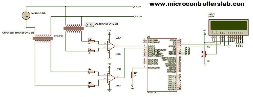 umed by the inductive load (fan), uses LM358 (op-amp), then using a specific code, it sets a timer, from the moment the voltage tends to 0, until current tends to 0. Then according to this timer, pf is calculated as delay between voltage and current crossing zero. I have found the following tutorial related link. In the above link, img1 is used as prototype schematic, where a shunt transformer from 240 to 5V is connected between fan terminals, and a series current transformer is also connected between one terminal of the fan. The two terminals of the two transformers, are connected to current/voltage limiter of 4kΩ, then fed into an LM358 opamp, then directly connected to analog input of PIC (in the link the PIC used is PIC16F877). Is that circuit (img1) safe to use? Also if the circuit is safe, and ideal to be practiced, what is the current transformer ratings? What is the maximum input current to the PIC analogue pin? Read more
Defining in-function local variables RS485 -I am having an RS485 communication problem between two PIC microcontrollers. After a while (10 minutes to more than one day), some unexpected data changes happen. There are no hardware problems. Previously it could hang after working similar periods. I have reduced these by disabling interrupts while EEPROM writing processes. Read more
Problem with MCP23017 expander – I am using dsPIC30F5011 microcontroller and I want to control dip switches through an IO expander. In between dip switch and IO expander, I connected a UNL2803 driver IC. I tested it for LED on/off but it is also not working. Read more
Multi-tasking with PIC controller for stepper motors – I have a 6 x 2 LCD, 3-button keyboard, three stepper motors, two temperature sensor and two heaters. I have tested my project without motor control codes. But when I was writing codes for motor control, I found that the motor codes run every time. If I execute other codes, the motor controlling output pulse is disturbed. Read more
PIC18F2550 SPI with MCP4922 – I’m facing a problem interfacing serial DAC with PICf2550. I tried simulation and it works but the hardware is not working. I’m trying to generate modified sine and cos waves. I think there might be something I’m doing wrong with configuration bits or maybe the SPI is different. Read more
Need help with 16F877 – I was using 12cXXX & 16FXXX & it was good for my small projects But now I need more stuff of it so I’ve decided to move to 16F877. But I couldn’t set trisA pins and MPLAB gives me errors when I start to compile it. Can anyone help me with any assembly code to light an LED on any port? Read more
Simple C problem – I’m using MikroC Pro for PIC24. My hardware uses an electronic attenuator chip that works just fine. I can program it to attenuate for 0 (full volume) to 127 (minimum volume/mute). That works great. Simple stripped down code below, raises and lowers the volume thru the full range of the chip (works). I left off obvious declarations, etc for clarity. Instead of attenuation, I want to have the volume increase from minimum at 0, to maximum at 127. I should be able to simply do the following to subtract ‘i’ from 127, right? It doesn’t work. I’ve tried unsigned, signed, shorts, chars, ints, variables of 127 in place of literals. What am I not seeing? Read more
voltage feedback control loop -I’m trying to implement a reliable feedback control loop for the output voltage of a sine wave inverter. The inverter has a MOSFET full-bridge driven by some PMW signals generated by an MCU. I have defined an extended look-up table to set the output voltage (from 33% to 97% of the maximum amplitude in steps of 0.5%). Thus I have a bidimensional array with 129 rows (the above mentioned attenuation) and 100 cols (samples per half wave). The problem is I don’t get a fast response (thus I got a poor voltage regulation) no matter what scenario I’ve used. I want to avoid intensive computing hence I have defined that large(?) array. Maybe I need even smaller steps (0.25%)? For now, a single step means +/-0.5% x 225 Vrms = 1.125 Vrms. The output voltage seems to stay in range but it fluctuates very quick (I’m using a halogen lamp for testing and it’s flickering quite annoying).Could anyone suggest any fix? Read more
CP2101 USB to UART bridge and Atmega 328P circuit questions – I am developing a circuit based on Atmega328P (8MHz 3.3V) and I want to add a CP2102 USB to UART Bridge from Silicon Labs. (CP2102 data-sheet). The device is powered from the external 12V AC-DC power supply and Atmega328p is powered by ASM1117 3.3V voltage regulator. The problem is that I can’t figure out if I can connect the 3.3V output pin from CP2102 to 3.3V line of the PCB to be able program the Atmega328P when the external 12V power supply is OFF AND and when the external 12V power supply is ON also. Read more
Most powerful ARM microprocessor for automation industrial automation – I am going to buy a demo board from Texas Instruments for automation applications but I haven’t worked in this area before. So I don’t know what kind of microprocessor may I need. Can you recommend a microprocessor from TI? Read more
Leave a Reply