What autonomous vehicle developers need to know about inertial navigation systems.
James Fennelly, Acienna inertial measurement systems
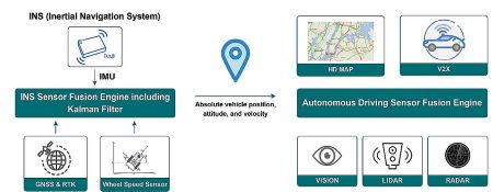
The inertial navigation system (INS) is essential to autonomous vehicles. It provides timing information for sensor synchronization and rapid updates of velocity, position, and attitude needed for the ADAS (advanced driver assistance systems). It complements perception sensors for localization.
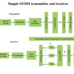
For highly accurate localization with high availability, the INS must contain a dual-frequency Global Navigation Satellite System (GNSS) receiver with real-time kinematic (RTK) abilities and a high-performance inertial management unit (IMU). Integrity monitoring in the INS—where the navigation system detects faulty measurement sources before they corrupt the outputs–is also crucial for automotive applications. In extreme cases when the environmental adversity causes the perception sensor and the GNSS receiver to fail intermittently or permanently, the ADAS can continue to work based on dead reckoning thanks to the self-contained nature of the IMU.
“Where am I?”
The answer to this question is critical for the successful, safe operation of self-driving vehicles. How does the autonomous vehicle accurately know where it is? The answer is the INS. An INS system is typically composed of a GNSS receiver, an IMU, and some pretty advanced algorithms.
The INS uses standard positioning techniques to generate location with an accuracy of a few meters. For autonomous driving applications that require lane-level accuracy, additional carrier-based positioning techniques, such as RTK, are required for centimeter-level accuracy.
For instance, say the vehicle is approaching a fork on the highway. The lane usually widens. Having centimeter-level accuracy can help autonomous vehicles better execute the sharp steering motion and make for a safer and smoother exit from the highway.
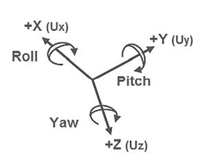
An IMU is often composed of two sets of sensors – three gyroscopes and three accelerometers. The gyroscope measures the angular rate of three orthogonal axes. Integrating the angular rate along the three axes over time generates roll, pitch, and yaw values which define the attitude of an object. Similarly, the accelerometer measures linear acceleration in three orthogonal axes. Integrating acceleration over time provides velocity, and integrating velocity over time yields distance traveled. An IMU with gyroscopic and accelerometer sensors can provide measurement over six degrees of freedom (6-DOF).
Why IMUs may include a magnetometer
An accelerometer can also be used to calculate roll and pitch values with respect to earth’s gravitational force and correct gyroscope drift. However, accelerometers cannot be used to detect
yaw because the change of yaw is orthogonal to the gravity vector. With regard to the earth’s magnetic field, the magnetometer measures the magnetic field strength in three dimensions. It can help to determine heading (i.e., yaw) as well as roll and pitch of the object. A magnetometer in the IMU can help with detection of the initial heading of an object and correct integration errors of the yaw gyroscope in the sensor fusion algorithm.
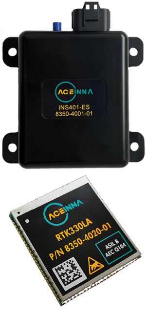
In Aceinna’s inertial products, such as RTK330LA, three IMUs are used to construct a triple-redundant sensor architecture. With Aceinna’s proprietary fusion algorithm, the system only uses valid IMU measurements. Any defective sensor output or errant dataset can be ignored or down-graded in importance.
When the GNSS signals are blocked by a tunnel, a covered parking lot, tall city buildings or even heavy foliage, the INS can use the IMU measurements to continue to compute positions, velocities, and attitude. This technique is called dead reckoning. When GNSS conditions are good, the GNSS receiver generates continuous positions and velocities which are used to constrain the INS estimates. When GNSS conditions become poor, the INS continues to output positions, velocities, and attitude based on dead reckoning for ADAS-enabled navigation.
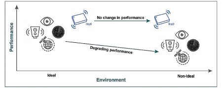
For L2+ autonomous driving, the autonomous vehicle must know the surroundings in order to navigate. It needs to be equipped with perception sensors and/or HD maps to gauge the traffic, what is ahead of the vehicle and beside the vehicle, the speed limit, and so forth. The INS can provide precise position, velocity, acceleration, attitude, and time. Unlike with the perception sensors, IMU operation is independent of the environment.
If the perception sensor fails because of adverse environmental conditions—for example snow, rain, or dust—the IMU can continue generating rotation and acceleration measurements so the INS can operate. To maintain ADAS features such as lane keeping, lane centering or hands-off on highway, the INS is fundamentally needed because it provides absolute positioning and redundancy in the vehicle. The INS is also used to precisely synchronize and stabilize perception sensors in an autonomous driving system.
For GNSS receivers, the key to high-accuracy positioning is the ability to resolve errors in distance and time from the satellites to the receiver antenna. When the satellite signal travels through the atmosphere, the ionosphere can delay the signal reception. The ionospheric error is a major contributor of errors to achieving centimeter-level accuracy. The dispersive nature of the ionosphere results in an ionospheric delay that varies depending on the frequency of the signal. A GNSS receiver that can track dual frequencies, e.g., L1 and L2, can compare the delays of these two signals and correct for the ionospheric error.
Tracking signals from multiple constellations enables a GNSS receiver to increase its availability. When obstructions block one signal, the receiver can utilize a signal from another constellation to stay online. If in a rare occasion a constellation fails, the GNSS receiver can still have access to the other constellations and ensure the availability of the solution.
The measurements provided by the IMU can include several error sources. When the INS is integrating the measurement samples, errors also accumulate. The INS needs an external reference to correct those errors and correct its position drift. The odometer is also an external reference. It provides independent measurement of displacement and velocity of the vehicle to aid autonomous navigation and reduces errors.
The integrity of a system describes how trustworthy the autonomous guidance system is. The positioning accuracy is calculated in post-processing when comparing the unit-under-test to the reference (i.e., the true position). In real time, the accuracy of the INS is unknown and its trustworthiness uncertain. An integrity monitoring system will have a protection level and an alert-limit parameter. The protection level is a statistical bound error computed for each positioning system calculated and the alert limit is determined by the application. When the protection level exceeds the alert limit, the integrity monitoring system will raise an alert and warn the user that the INS is either unavailable or possibly generating misleading information. Integrity monitoring is critical for applications that could affect safety of life.
Another factor to consider is the operating and support costs. L2+ autonomous driving via perception sensors and HD maps would require cloud infrastructure and maintenance and a lot more processing power in real time. These measures would add significant cost to the autonomous driving system. Correction providers would also need to charge a fee for service subscriptions to maintain their infrastructure and expand their coverage.
Fortunately, technologies for MEMS INS are developing at a fast pace, keeping down INS costs. Critically, when used with other perception sensors (cameras, radar, lidar), precise positioning helps cars anticipate the next maneuver and increase the safety and quality of the ride. Precise positioning in autonomous vehicles can also improve the performance (safety, reliability etc.) of many ADAS functions such as lane centering, lane change assistance, and lane departure warning.