Digital clocks are everywhere. In fact there are too many clocks around. If you do a quick sweep with a spectrum analyzer, then as well as the frequencies you might expect to see – local TV and radio stations, cellphones and WiFi signals – you will find all sorts of other spurious signals from the equipment in you house/office/pocket. Most products have some digital element and that means a clocked device. It might be a microcontroller or FPGA but it will also probably be communicating with some other chip locally or other devices it is plugged into. In the past you would have found microprocessors with strange clock frequencies simply because it could simply be divided down to a convenient baud rate for serial communications e.g. 7.3728MHz crystals – if you divide by 2 enough times you can obtain many convenient baud rates from 115200 downwards.
Now there a phase-locked-loop (PLL) based clocks everywhere as well as programmable dividers so we aren’t constrained with such crude clock choices. We can pick one clock for the microcontroller or FPGA and use PLLs to produce higher frequencies and programmable dividers to produce lower frequencies. There are even clock chips around that will produce pretty much any frequency you like from your input clock. All these clocks can cause problems though. You now have small transmitters on your circuit board and because the clock edges are reasonably fast, they create a huge number of harmonics, mainly odd harmonics, meaning 3rd, 5th, 7th harmonics etc. If you have any sensitive analog circuitry nearby or on the PCB then you could have a problem. You could also fail EMC compliance tests.
One way of reducing the interference caused by digital clocks is to use spread spectrum clocking. This involves generating a clock that varies slightly in frequency around the central, desired frequency. It has the effect of “spreading” the frequency spectrum of the clock. The ON Semiconductor AND9015 application note illustrates the effect:
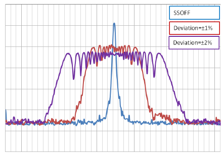
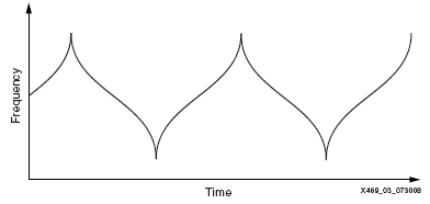
With spread spectrum turned off there is a single dominant peak of emissions at the frequency of the clock. With spread spectrum turned on there is a spread of frequencies emitted by the clock, centered around the clock frequency in this case so the average frequency is maintained. The amount of the deviation (modulation depth) affects the peak spurious signal level but the modulation rate and modulation profile also affect the resulting spectrum. The modulation rate is usually in the audio frequency range. A logical modulation profile would be linear i.e. the frequency is linearly changed from one extreme of the frequency modulation to the other and back in a linear fashion using a triangular modulation profile. However, the Hershey’s Kiss or Lexmark modulation schemes further reduce the peak emissions. The frequency versus time profile of Hershe’s Kiss modulation is shown below, from the Xilinx Application note XAPP469.
Other modulation schemes may also be used such as sinusoidal and sharkfin. The sharkfin modulation is based on an exponential capacitor charge/discharge so is easy to generate, but not as effective as Lexmark or Hershey’s Kiss, though better than linear. Note that increasing the amount of deviation has a diminishing effect. While a small deviation of only 0.5% can make quite a significant reduction in the peak emissions, increasing it more and more has progressively less effect. This can be seen in the earlier ON Semiconductor graph.
Also, bear in mind that you are not actually reducing the emissions if you consider total energy radiated, you are just spreading it around so the peaks are lower. However, emissions regulations look for a peak level of radiation not the average power or energy so spread spectrum clocks do help squeeze under the allowed levels.
The interference caused by the clocks are not confined to the direct clock but also to any clock derived from the original clock. This can include the address and data lines of external memory for example. These lines can be the antennae causing excess emissions because they are often longer than actual clock routing, which can usually be fairly short and direct.
If your microcontroller or FPGA doesn’t have the option for spread spectrum clocking you can easily add it by using one of the many spread spectrum clock generation chips. These usually take an input clock and produce a spread spectrum output clock. The simplest will produce a 1:1 output to input clock ratio i.e. the frequency is unchanged. More complex devices will offer a programmable peak deviation and multiple clock outputs with various programmable multipliers/dividers using the internal PLL (phase locked loop).
Leave a Reply