
(editor’s note: Intrigued by the problem? Have a similar challenge? Have a question or another solution? Then click the “Read more” link and follow the conversation on EDAboard.com or log in to EDAboard and participate in the microcontroller forums.)
Button key navigation menu data value – I am struggling to get the updated values from the navigation key while updated values on the LCD. The Up and Down Key increments or decrements the values of the corresponding variable. The Right and Left key changes the position of the LCD as well as the variables. And the Okay button exits the loop and saves the variables to a structure. How can this in an efficient way? Read more
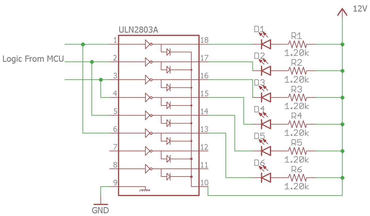
ULN2803 with LED with 12V VCC – I have a circuit shown below. The problem is that the ULN2803 is often broken after the circuit running is for 1-2 days. Is there anything wrong in my circuit? Read more
Generating PWM with PIC33 – I need help using a DSPIC33FJ32MC204 to generate PWM in which two PWMs generate in 180-degree phase angle with equal duty cycle. Read more
Video camera project – I would to use a camcorder as a PTZ camera. Data from the camera is necessary processed from a microcontroller and stored. What camera do I choose for this project? Is it possible to implement this project with a PIC24 microcontroller? Read more
How to do generate a second interrupt – I need to generate a second interrupt for LED2. There are 3 LED lights, Red, Green, Yellow.
Step 1: I want Red LED to turn on and blink 4 times per second for 10 seconds, then turn off.
Step 2: After that, I want Green LED to turn on and blink 6 times per second for 15 seconds, then turn off.
Step 3: Finally, I want Yellow LED to turn on and blink 8 times per second for 20 seconds, then turn off.
I want to repeat steps 1 through 3 until I turn off the power. Read more
#include<reg51.h>
sbit led1 = P1^0; 		//LED connected to P0 of port 1
sbit led2 = P1^1; 		//LED connected to P1 of port 1

void timer(void) interrupt 1 		//interrupt no. 1 for Timer 0
{
	led1=~led1; 		//toggle LED on interrupt
	TH0=0xFC;		// initial values loaded to timer
	TL0=0x66;
}
main()
{
	TMOD = 0x01; 		// mode1 of Timer0
	TH0 = 0xFC;		// initial values loaded to timer
	TL0 = 0x66;
	IE = 0x82;		// enable interrupt
	TR0 = 1;		//start timer
	while(1);		// do nothing
}
GPS and GSM using Atmega 8 – I want to connect both a GPS receiver which has a TTL logic and a GSM modem to Atmega 8. How do I connect GPS and GSM to a microcontroller since it has only one USART? I want to use a MAX485. Read more
Split string – How do I split a string according to the delimiter? My code has an error on line 1 and line 5. Read more
Five microcontrollers communication using UART – I am trying to communicate five microcontrollers using a UART with 1MHz freq and 2400 baud. All five MCUs are ATmega32. The problem is that there is a never-end loop in main and I don’t want to interrupt it while receiving and transmitting data. It is working properly when I’m doing it with two MCUs. But now I need to go beyond this and I’m using 5 MCUs. Read more
Programming using PIC18f4580 – I must control the detection of distance by using an ultrasonic sensor. I must use PIC18F4580. My problem is that I didn’t get correct program code. Read more
UART problem in sim800 – My task is to simply check the received message from a particular number. If yes, then the relay will operate and there is an acknowledgment message from a SIM800 module to the sender. My problem is the message function. I can operate relay but as I insert a function to send a message, the code will not work properly. Read more
Leave a Reply