• Skip to primary navigation
  • Skip to main content
  • Skip to primary sidebar
  • Skip to footer

Microcontroller Tips

Microcontroller engineering resources, new microcontroller products and electronics engineering news

  • Products
    • 8-bit
    • 16-bit
    • 32-bit
    • 64-bit
  • Applications
    • 5G
    • Automotive
    • Connectivity
    • Consumer Electronics
    • EV Engineering
    • Industrial
    • IoT
    • Medical
    • Security
    • Telecommunications
    • Wearables
    • Wireless
  • Learn
    • eBooks / Tech Tips
    • EE Training Days
    • FAQs
    • Learning Center
    • Tech Toolboxes
    • Webinars/Digital Events
  • Resources
    • Design Guide Library
    • DesignFast
    • LEAP Awards
    • Podcasts
    • White Papers
  • Videos
    • EE Videos & Interviews
    • Teardown Videos
  • EE Forums
    • EDABoard.com
    • Electro-Tech-Online.com
  • Engineering Training Days
  • Advertise
  • Subscribe

How to accurately measure header/connector pitch

September 20, 2017 By Scott Thornton 6 Comments

Sometimes when you’re working with a microcontroller unit evaluation board, you need to connect a ribbon cable to the board’s header. If the ribbon cable isn’t specified, how do you know what to order that will fit the header on the MCU board? The pitch of a connector refers to the distance between the pins on a connector. If you don’t have a datasheet or a known part number for a connector, determining the pitch of the connector can be difficult, especially if the distance between the pins (pitch) is very small (often the case).

A pin header, often simply called a header, is an electrical connector with one or more rows of exposed male pins set in a plastic base. A header with female connections is referred to as a header connector. A header or header connector is often a main junction or connection point for interfacing one piece of equipment or device to another. Headers are used to connect with a ribbon cable, or as “jumpers” where electrical connections are made from pin-to-pin or where alligator clips can be temporarily attached.

Figure 1: The pitch of a header is measured from the center of one pin to the next (A). For accuracy, one can also measure from outside edge of the first pin to the inside edge of the last pin (B), in which case A = B/(C-1). (Source: KCR)

A jumper can also be called a shunt and is used to quickly connect one pin or terminal to another. Many development boards use a jumper instead of a switch. For example, you might have to set a jumper for boot-up mode and then move the jumper to another position for programming mode. A header with just one pin is a test point. Other names for headers are: board-to-board connectors (for connecting printed circuit boards to each other), terminal strips, pin strip headers (usually a single row of pins set in a plastic base) and board stackers (since they can be used to set a daughter card, for instance, on top of another board). For the newest of newbies, you might want to know that a male connector has pins and a female connector is also called a receptacle and has holes. Putting them together is called mating (I didn’t make this stuff up, folks. But someone has to tell the newbies about the birds and the bees in the electronics world.)

Connector pitch (distance between pins)

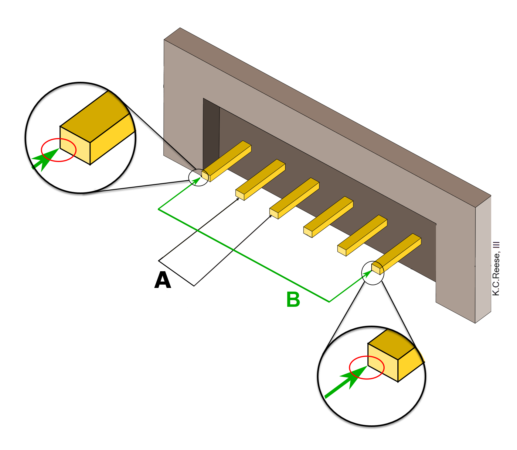
The pitch of a header is measured from the center of one pin to the next (Figure 1, measurement A). If that’s difficult to do with accuracy, you can measure pitch another way. Referring to Figure 1, to measure the pitch (A) of a pin header, measure from the outside edge of the first pin to the inside edge of the last pin (B). Then count the number of pins in the row (C). The pitch, equivalent to A, is equal to B/(C-1), or A = B/(C-1).

If there are two or more rows of pins on the header, then you will want to measure the distance between each row as well. The pitch of the connector is not always the same as the pitch of the ribbon cable, however. A two-row connector with pin spacing at 0.1 inches (2.54 mm) will require a ribbon cable pitch at half of the connector mating pitch, or 0.05 inch (1.27 mm, the most common pitch on ribbon cables).

Figure 2: Ribbon cable is usually either gray or rainbow. The red stripe is intended to indicate the pin one conductor of the gray cable. The header on the rainbow cable is an IDC connector header and cuts through cable insulation and somewhat into the conductors in the ribbon cable so as to make a good electrical conductor.  (Source: Wikipedia, User: Heron)

To measure the pitch of a ribbon cable, measure the cable from outside-edge to outside-edge of the cable, then divide by the number of conductors. Ribbon cable conductors are also called “ways.” This means that a ribbon cable with eight conductors would be called 8-way ribbon cable. Most rainbow-hued ribbon cables are colored in order of resistor values. The red stripe of an all-gray ribbon cable usually means that the red conductor is connected to pin 1.


Filed Under: FAQ, Featured, microcontroller Tagged With: basics, FAQ

Reader Interactions

Comments

  1. Yannick says

    June 19, 2019 at 8:06 am

    Is your first image correct? A appears to be demonstrating the distance between a pin and another pin that is 2 pins away, not an adjacent pin. The verbal description seems to contradict the image and its confusing.

    Reply
  2. Aimee Kalnoskas says

    July 2, 2019 at 6:20 pm

    Yes, you are right! Fixed!

    Reply
  3. Jack says

    March 11, 2020 at 9:45 pm

    Cool article but now the diagram shows the measure from the center of one pin to the left edge of the adjacent pin. I think this is meant to be a center-to-center measurement.

    Reply

Leave a Reply Cancel reply

Your email address will not be published. Required fields are marked *

Primary Sidebar

Featured Contributions

Five challenges for developing next-generation ADAS and autonomous vehicles

Securing IoT devices against quantum computing risks

RISC-V implementation strategies for certification of safety-critical systems

What’s new with Matter: how Matter 1.4 is reshaping interoperability and energy management

Edge AI: Revolutionizing real-time data processing and automation

More Featured Contributions

EE TECH TOOLBOX

“ee
Tech Toolbox: Internet of Things
Explore practical strategies for minimizing attack surfaces, managing memory efficiently, and securing firmware. Download now to ensure your IoT implementations remain secure, efficient, and future-ready.

EE Learning Center

EE Learning Center

EE ENGINEERING TRAINING DAYS

engineering
“bills
“microcontroller
EXPAND YOUR KNOWLEDGE AND STAY CONNECTED
Get the latest info on technologies, tools and strategies for EE professionals.

RSS Current EDABoard.com discussions

  • CST Studio – How to increase frequency step size (e.g. to 100 MHz)?
  • What is the difference between MIMO antenna elements arragned radially across the pentagon shaped substrate versus rectangle shaed substrate?
  • General purpose CMOS Op Amp and PMOS & NMOS from LTSpice library
  • Simple Active Bandpass Filter Oscillates
  • TMP117 > Can not read temperature on LCD

RSS Current Electro-Tech-Online.com Discussions

  • Capacitive Touch On The Profile
  • JBL charge 4 dead motherboard?
  • Guitar electronics project
  • can a AT89C51 be used as a rom?
  • going out on a limb and praying the schematic is correct

DesignFast

Design Fast Logo
Component Selection Made Simple.

Try it Today
design fast globle

Footer

Microcontroller Tips

EE World Online Network

  • 5G Technology World
  • EE World Online
  • Engineers Garage
  • Analog IC Tips
  • Battery Power Tips
  • Connector Tips
  • DesignFast
  • EDA Board Forums
  • Electro Tech Online Forums
  • EV Engineering
  • Power Electronic Tips
  • Sensor Tips
  • Test and Measurement Tips

Microcontroller Tips

  • Subscribe to our newsletter
  • Advertise with us
  • Contact us
  • About us

Copyright © 2025 · WTWH Media LLC and its licensors. All rights reserved.
The material on this site may not be reproduced, distributed, transmitted, cached or otherwise used, except with the prior written permission of WTWH Media.

Privacy Policy