How can you make your resume really stand out? This has been the topic of books, articles, class assignments, and blogs for decades. It came up in conversation one day, and a friend of mine had a unique story. I’ve included it below, with some edits.
“With so much written on the topic, there is one resume that still sticks with me thirty-five years later. In the mid-1980s I was working as an electronics technician for a component manufacturer. The department had an opening to expand and hire a second technician. Before the internet, jobs were typically placed in a newspaper “want ads” with candidates mailing in the resumes and cover letters via U.S. mail. Among all the stacks of letters, my supervisor received one package about the size of a shoe box. Inside the box was a device that had an array of alphanumeric LED displays on its cover and written instructions on how to plug the device in and turn it on. After following the instructions, the red LED display lit up and started to scroll the applicant’s cover letter and resume in a continuous loop, which I still remember.
The applicant worked for Franklin Computer at the time. Franklin Computer was known for pocket dictionaries, spell checkers, and even an electronic Bible. In the mid-1980s they attempted to market Apple IIe clones.1 Unlike the easy availability of similar devices today, through his employer the applicant had access to resources so he could program and burn his resume to non-volatile memory chips of the day and program a Microcontroller (MCU) to display it. Along with catching our attention, it also demonstrated his skills and ability to contrast against others with a custom device. He got the job.
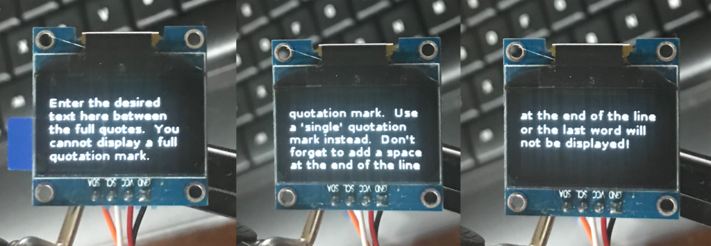
Recently, a client wanted an Arduino design that would remain dormant for up to 20 days in a dark box that would be delivered by mail. When the recipient opened the box, a custom message would scroll across a 1.3” OLED display. I accepted the project. It was a young web designer that wanted his resume to stand out among his competition. He planned to purchase a low-cost Arduino and OLED displays, assemble them into a custom package, and mail them to hiring managers at companies where he was going to apply. The client knew that what he was asking for was technically possible but didn’t have the skills to execute it. I was happy to take the assignment and create my oven version of the electronic resume display I had seen 35 years ago.
Having an Arduino scroll a message across an OLED display is relatively easy with available opensource libraries. Some custom programming was necessary to get the text to display word by word, as requested. Wiring between the Arduino and chosen OLED display was simplified by using a two-wire I2C interface. Detecting when the box had been opened was just a matter of using a photoresistor (a Light-Dependent Resistor) in a voltage divider across the Arduino’s external interrupt. But what about the 20-day power requirement? With only seven days to complete the entire project, how could I guarantee that the battery selection of the finished design would last 20 days? With some careful design consideration, reading the specification, and actual measurements, the deliverable design far exceeded the 20-day requirement. The design was validated by actual testing later.”
Eliminate the USB in favor of FTDI chip
One of the biggest advantages in developing on an Arduino microcontroller board is the ease of writing code using Arduino’s Integrated Development Environment (IDE) and then downloading it the to the Arduino board with a common standard-A to micro-B USB cable. However, like everything else, convenience comes at a cost. Arduinos with onboard USB support will consume additional power, even when they are not powering the Arduino via USB. On an Arduino UNO board, the USB support costs an additional 15mA. Fifteen milliamps may not seem like much, but it could significantly impact the ability of an entire design like the above to last 20 days.
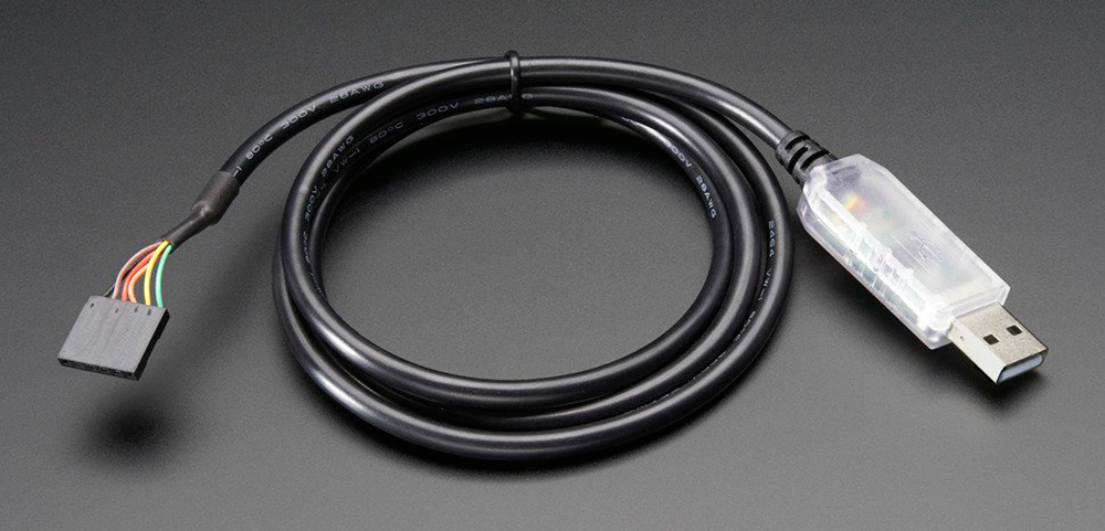
On the other hand, some Arduino boards can be programmed using an FTDI cable. FTDI is a company that’s been manufacturing USB-to-serial converters for several years. (It’s important to only buy genuine FTDI products since counterfeit chips may not work well.) A genuine FTDI cable for this purpose costs about twenty dollars. The FTDI cable itself has an embedded chip that converts the computer-side (host) USB signals to Transistor-Transistor Logic (TTL) serial signals on the Arduino. When the USB circuitry moves from the Arduino to onboard the FTDI cable, there is no additional power drain when the Arduino is being powered by a battery. One such Arduino that supports FTDI programming is the Arduino Pro Mini. The Arduino Pro Mini 328 and Arduino Pro 328 are each available in two versions; both offer a choice of 3.3V running at 8MHz or 5V at 16MHz. So how do you evaluate the best selection for this design?
Choosing based on voltage level: 5Vdc or 3.3Vdc?
Most microcontrollers designed to run on Arduino boards typically come in either 5Vdc or 3.3Vdc logic level versions. The 5Vdc logic level comes from the legacy Vcc levels of the TTL serial technology dating back to the 1970s. The 5-volt logic level comes from the semiconductor processes and performance characteristics of the time. As such, many peripheral components like sensors and drivers were designed around these logic levels. 5Vdc logic level devices are still prevalent today as fully functional remnants of electronics in earlier times.
Advances in semiconductor processing have allowed lower voltage level highs at 3.3v, where 3.3v became the logical bit “1”, rather than 5v. Using a five-volt blip to register a logic level 1 consumes more energy than a 3.3-volt level for a logic level 1. (Near zero voltage level registers as a logic level 0 for both.) Thus, CMOS technology has created alternatives for TTL to perform the same functions at lower voltage levels. Lower voltage levels equal lower power consumption. Lower power consumption equates to longer battery life. Without any specific power calculations, choosing an Arduino that supports 3.3Vdc logic is the better choice. (Semiconductor process technology has brought voltage supply levels even lower, saving more power, but Arduinos don’t support voltage levels lower than 3.3v .)
Choose 8MHz or 16 MHz?
The driving goal of semiconductor development is faster and faster processor speeds. Other than cost, it seems rare that a designer would ever choose a slower processor speed over a faster one. However, remember that the faster the processor speed, the more heat that is dissipated by the processor. That’s why the latest computers will have a huge fan-cooled heat sink mounted directly on top of the processor chip. Taking a step back and looking at the OLED display design mentioned earlier, nothing in the design requires the top clock speed of 16MHz offered on the Arduino Pro or Mini Pro. The difference is just nanoseconds if you detect the opening of the box using an 8 MHz clock versus a 16 MHz clock, which is imperceivable to the user. The words displayed on the OLED display is in the range of hundreds of milliseconds at a time. By choosing the lower clock speed of 8MHz over the 16MHz, there’s no degradation in performance, and the MCU is consuming less power.
Power consumption evaluation
With our Arduino and OLED display chosen, what is our starting point for sizing the batteries to last 20 days? While we could continue to pour over the component documentation, there is no substitute for measuring the current draw of the circuit with a milliamp meter. Using the milliamp setting of a multimeter and attaching the probes as needed, we can see that we’re drawing about 15mA for the Arduino and OLED display. So, what size and how many batteries will we need to last 20 days? To calculate this, we need to look at the “milliamp-hours” each type of battery can supply.

Battery mAh capacity by type
While the ambient temperature and current draw influence battery life, it’s simpler to use the “milliamp hour” (mAh) rating for each alkaline battery size in Table 1 below. Note that since mAh refers to the amount of current the batteries can supply, connecting batteries in series to achieve the desired output voltage does not increase the mAh. One AA battery will supply 1.5Vdc for 2400 mA hours. Three AAs in series will supply 4.5Vdc for 2400 mA hours. You would have to connect the batteries in parallel to extend the capacity (in milliamp hours).
Calculate the number of days each battery type will last using the formula:
Days = (Capacity (mAh) / 15mA) x 1 Day/24 hours
You can get a maximum battery life out of the 6-volt lantern battery or a series of D batteries. Two D cells would provide 3 volts. However, that would put the supply at the low-end range of the selected 3.3V Arduino. While it would initially work, the batteries would only have to drain a few hundred millivolts before you’re out of range for a 3.3V Arduino. Therefore, it’s better to use three 1.5-volt batteries so that the batteries can drain by 33% before the supply starts to get into the problematic range.
Arduino deep sleep mode
The above is technically a solution, but a lantern and three D cell batteries are bulky. If bulky batteries are a problem, then you need to look at reducing the current draw of the system by implementing the “deep sleep mode” of the Arduino microcontroller. In deep sleep mode, the processor is halted until an external interrupt wired to the light sensor “wakes up” the Arduino and resumes the program. Since the processor is not running, only a small amount of current is used to monitor the external interrupt. After implementing the deep sleep mode, the supply current measures 1.9mA.

You now have more choices to meet the 20-day requirement, as shown in Table 3.
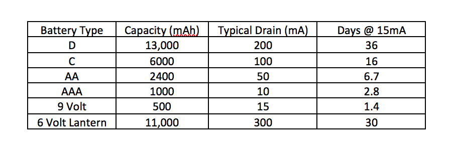
While AAA batteries meet the 20-day requirement, the AA batteries are a better choice, lasting more than twice the 20-day requirement and taking up not much more room than AAA batteries. AA batteries are significantly smaller than the C, D, or lantern battery choices.
OLED sleep mode
Although the OLED display has a sleep mode, it’s not worth implementing for this use case. While the Arduino is in its sleep mode, the OLED can be set to have all LEDs off. The display’s backlight LEDs in the off state reduce the current that’s drawn by the OLED, but the driver chip may be running at full power, albeit low. Implementing an OLED sleep mode might get the 1.9mA circuit current draw to under 1mA, allowing more confidence in selecting the AAA batteries, but the higher cost of AA batteries is worth the time and effort saved, considering that the scope of the project was a one-off shoe-box message delivery system. If you were building hundreds or thousands of these devices, it would be worth the time to design the lower current draw of the OLED driver, as well. However, for a dozen or so shoe box messaging systems, it isn’t worth it. Judgment calls regarding what is “good enough” to balance cost, schedule, and specification are all part of good engineering.
¹ Franklin Computer was sued by Apple in a landmark case that established that compiled software code and computer operating systems are copyright protected. This forced Franklin Computer out of the desktop computer market. This loss for Franklin Computer is probably why the technician was looking for another job in the mid-1980s. Ref: https://en.wikipedia.org/wiki/Apple_Computer,_Inc._v._Franklin_Computer_Corp

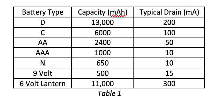
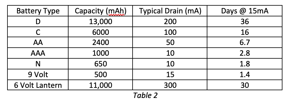


Your second table is identical to the first. I was expecting a table that showed the standby times for each battery versus 1.9 mA.
I noticed that too. To get the correct table, I suppose we can just by 1.9mAh instead of 15mAh. That being said, thank you so much to the author! This post was really helpful and informative!