Powering an Arduino has a little magic to it. It wasn’t obvious to me when I first started working with them, but Arduinos have on-board regulation. Taking advantage of this allows for longer power supply wiring runs by using a higher voltage power supply than the nominal 5V or 3.3V needed by the microcontroller (MCU) for logic levels. Some Arduinos accept 6Vdc to 16 Vdc of input voltage, which is well above the maximum rating of the MCU, but the Arduino board regulates the supply voltage accurately as well as additional power for Arduino peripherals. I’ve seen veteran engineers baffled as to the reasoning behind powering a 3.3V Arduino with a 9Vdc power supply until it’s been explained to them.
Microcontroller power requirements
Selecting an appropriate power source for microcontroller-based designs is often overlooked. While concentrated effort and forethought may be in the details of the design itself, many performance and reliability problems can be traced back to the selection and connectivity of the power source. The Arduino family of development boards provides solutions for these problems, but it’s easy to get it wrong without a good understanding of what options are available when you’re designing it. It’s not as simple as saying that a 5V Arduino uses a 5Vdc power supply and a 3.3V Arduino uses a 3.3 Vdc power supply.
Arduino power requirements
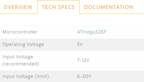
Many Arduinos use the ATmega328P microcontroller. Microchip’s ATmega328 has a wide range of acceptable Vcc voltages. (Vcc is the regulated DC supply voltage needed to operate an IC and is often referred to as a supply voltage for ICs.) Most commonly, Arduinos are designed to work at either a 3.3 V level logic for low power consumption or 5 V logic to be compatible with legacy TTL logic devices. The examples provided below refer to 3.3 Vdc devices where the power source considerations are more critical. However, the same principles apply to 5 Vdc devices.
Example: Arduino Pro Mini
First, let’s assume a circuit design that uses something like the Arduino Pro Mini. The maximum current draw of the Arduino is 200mA. It’s unlikely that the Arduino itself will draw 200mA, but let’s assume that between the Arduino and the other devices connected to it, they draw a total of 200mA. The ATmega328p datasheet shows that the minimum voltage of a logic high at a pin is 90% of Vcc. Thus, if Vcc is 3.3 Vdc, the minimum voltage at a pin that will be considered a logic high is 0.9 * 3.3 Vdc = 2.97 Vdc. Any value seen at a digital pin below 2.97 V is in an indeterminate range and will cause unpredictable results from the Arduino.
There is always some distance between a power source and an Arduino. The greater the distance, the greater the voltage loss across the power supply’s wiring. But how much is lost? Since 26 AWG is a common choice for low power circuit wiring and it’s on the smaller end of the range of wire gauges, there is less copper. Less copper means lower cost. Stranded 26 AWG is a good choice due to the flexibility of routing the wires. The 26 AWG is large enough such that it’s rated for carrying as much a 2.2Amps for chassis wiring, which is more than ten times the 200mA current draw we’ve specified for the Arduino’s maximum current draw for our design. A 3.3 Vdc power supply and 26 AWG seem like a great choice, but let’s take a closer look.
Power source line loss
Quality 26 AWG wire has a resistance of 40.81 ohms per 1000 feet or 40.81 milliohms per foot. With 200mA flowing through the power source’s wires, we’ll have a voltage drop per wire run as investigated below. Keep in mind that we need to run the wire from the power source to the Arduino and then back again the to the negative side of the power source. We can see that at ten feet, we’ve lost 5 percent of our 3.3 Vdc source. At 20 feet, we’ve lost almost 10 percent. This action reduces the voltage applied to the Arduino to just 4.5V; the low limit of our guaranteed maximum digital logic high voltage.
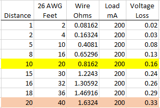
Twenty feet seems like a reasonable distance for most applications. However, we’ve only considered the resistance of the wire itself to this point.
Contact resistance
Contact resistance is often not considered or even understood. The resistance of the 26 AWG wire is 40.81 ohms per 1000 foot based on the cross-section diameter of the wire. However, every point in the wiring where we’ve placed a connection in the wiring, we have created a point where the cross section of the current path decreases, and therefore have a higher resistance point.
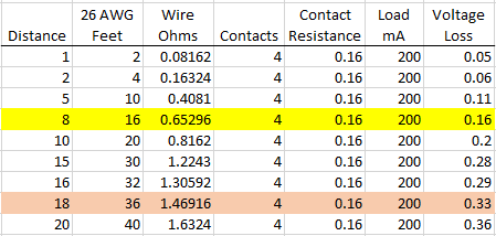
Mating a circular connector will only make the pin contact the barrel at a tangential point. Blade connectors produce the same reduced area across the surface. Even a screw terminal can’t match the cross-section resistance of the wire itself. Consider that any termination is susceptible to oxidation over time and increased resistance by connecting and disconnecting the wires multiple times over the life of the system. Each of these points can easily have a contact resistance of 40 milliohms. That’s right; each connection point can add the equivalent resistance of 1 foot of 26 AWG wire. With two connections landed on the Arduino and two connections at the power source, any system will have a minimum of 4 terminations. We now have a voltage source loss of 5 percent at 8 feet and 10 percent at 18 feet between the Arduino and its power source.
Single supply choice – varied distances?
Therefore, with a typical power source wiring setup, we’re losing five percent of the 3.3V source voltage between the power supply and Arduino at eight feet and 10 percent at 18 feet. In simple terms, if we were using an adjustable dc power source, we could increase the voltage to compensate for the line loss and contact resistance. However, power supplies are expensive and take up space. Typically, in embedded systems, designers try to have a common power source for multiple embedded controllers. If one controller is one foot away from the supply and the last one is 20 feet away from the power source, the designer has a delicate balancing act to keep each embedded controller within the proper range.
Arduino power source options
Arduino designs give you a way to work around the line loss and contact resistance power source problems by providing on-board regulation. However, there are several ways to power the Arduino and not all of them provide the benefit of on-board regulation:
USB Power – A USB cable is commonly used to program an Arduino through the Arduino Integrated Development Environment (IDE). Not only does the USB cable provide diagnostics through the IDE serial monitor, but it also offers 5Vdc power to the Arduino through the USB Vcc pin. The 5V USB power is used to power a 5V Arduino directly, or it’s regulated down if it’s a 3.3Volt Arduino.
5V or 3.3V Power – The designer can apply the appropriate voltage to the 5V or 3.3V power pins of the Arduino. These pins are tied directly to the power pins of the MCU on the Arduino board. However, applying power to these pins will cause the MCU of the Arduino to be susceptible to the line loss and contact resistance loss from the power source mentioned earlier.
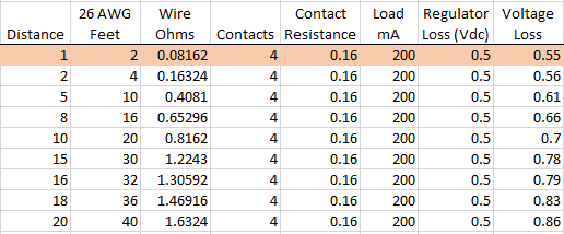
Vin or Raw – Arduino may have this pin labeled either “Vin” or “RAW” depending on the Arduino Variant being used. A common mistake is to apply a 5V or 3.3V power source to this pin. The problem with this is that not only do you have the line loss and contact resistance loss mentioned earlier but that this pin is the input to the on-board regulation circuit. Like any voltage regulator, you need to supply slightly more voltage into the device than you expect to get out of it. If we applied 3.3 Vdc to Vin, we would lose about 0.5 volts through the regulator. That means the microprocessor and connected peripheral devices would only be running on 2.8 Vdc, at best. Combined with our noted line loss and contact resistance loss, we can be running well below our required voltage level.
VIN pin, properly used
Despite the problem described above, using the VIN or RAW pins are the solution to the source voltage loss. On the Arduino board, the VIN or RAW pins are the input to the voltage regulator on the Arduino board. All we need to do is apply a voltage in the specified range to get the desired regulated output to the Arduino. A supply voltage of 6 Vdc to 12 Vdc applied to Vin, or RAW will power the Arduino’s microcontroller, overcome any line or contact resistance voltage loss, and provide power output to the 5V and 3.3V pins of the Arduino to power peripheral components. The range of the Arduino’s input voltage is based on the voltage requirements on the entire board, including the energy required for the MCU to powering peripherals.
Conclusion
Off-the-shelf power supplies within the range of 7 Vdc to 12 Vdc are not as common as 3.3Vdc or 5Vdc power supplies, but they are available. It’s tempting to use the more common 5 Vdc and 3.3 Vdc power supplies for Arduino boards, but from the facts presented above, it’s necessary to use the less common alternatives for the best regulation and microcontroller performance.


This is great… I’ve been working on a project using Arduino Uno and because of power issues/drop in voltage (could verify when the input being activated, the power and on board LED used to flicker), Arduino used to get jammed-more like non-responsive… And the only solution is sometimes it recovers on its own but mostly had to be manually rest.
Gonna adjust my 5V dc supply to give an output of 5.5 – 6V, and if that doesn’t help, I’m gonna replace it with a 9V SMPS.
I myself went quite in depth on the loss issue and how to power multiple arduino’s for home automation. One more thing that you may want to also consider is losses at voltage regulators. If you are using arduino’s voltage regulator you should consider it’s losses. Efficient regulators will loose about 5% of power. Higher loss is likely. Power supply will have similar loss. By using arduino’s voltage regulator you may be doubling up the losses at voltage regulators and you should consider it in your calculations. You may be better off having one efficient power source going directly to arduino.
This article would have been a bit better, had they tried a 12 V battery charger as a source. Not using a nominal 12 volt, but an proper charging voltage of near 15V. Upper limits are just as important as minimum ones.
Thanks for the good article. I have a question. I’m using Arduino Pro mini with the following connection:
– Tx, Rx, D4, connected to my external device which also supplies Vin (12v), GND
– Vcc, GND, D2, D3 connected to BN-180 GPS (consume max 50ma
The above connection is working fine without any problem.
As I’m going to put my HC-05+Max3232, both consume 60-70ma when waiting for pairing and reduces to less than 10ma when connected, into the same box as above and take the current from Vcc, GND pin on the same Pro mini board. Do you think the board can handle the load of the HC-05+Max3232?