• Skip to primary navigation
  • Skip to main content
  • Skip to primary sidebar
  • Skip to footer

Microcontroller Tips

Microcontroller engineering resources, new microcontroller products and electronics engineering news

  • Products
    • 8-bit
    • 16-bit
    • 32-bit
    • 64-bit
  • Applications
    • 5G
    • Automotive
    • Connectivity
    • Consumer Electronics
    • EV Engineering
    • Industrial
    • IoT
    • Medical
    • Security
    • Telecommunications
    • Wearables
    • Wireless
  • Learn
    • eBooks / Tech Tips
    • EE Training Days
    • FAQs
    • Learning Center
    • Tech Toolboxes
    • Webinars/Digital Events
  • Resources
    • Design Guide Library
    • DesignFast
    • LEAP Awards
    • Podcasts
    • White Papers
  • Videos
    • EE Videos & Interviews
    • Teardown Videos
  • EE Forums
    • EDABoard.com
    • Electro-Tech-Online.com
  • Engineering Training Days
  • Advertise
  • Subscribe

How to wire a switch to a microcontroller with pullup resistors

October 3, 2016 By Scott Thornton Leave a Comment

If you want a button or switch as an input on a microcontroller (MCU), you can use a “pullup resistor” so that the input is seen as a logical high when the (normally open) switch or button is closed. A pullup resistor is connected to Vcc, or logical high for your input, and therefore “pulls up” the value on the pin to high. The corresponding program or software will need to match the state of a normally open (N.O.) switch as high when the switch is closed. “Normally open” is just that; its natural state is open until you close the switch.

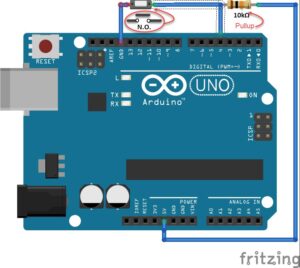
For some MCUs, the MCU itself may run at a different supply voltage (e.g., where Vcc = 5v) than what is used for the inputs (e.g., 3.3v), so make sure you know what your pins can handle. You would connect the pullup resistor like this on an Arduino UNO:
pullupdi4_nobutton_r2
Figure 1: A pull-up resistor on digital input 4 of an Arduino UNO Rev 3. (Drawn using free tool at fritzing.org)

If you have no pullup resistor, your input will still read a state, but whether it will read high or low is unknown, since nothing is physically assigned to it. The exception is if your MCU has an internal pull-up resistor. When nothing is tied to a pin, it’s commonly referred to as a “floating pin,” because it has no assigned state of high/low, and noise can randomly influence the voltage level on the pin if it’s left floating.

In Figure 1, if you press the button, the pin will be connected to ground, and the only reason it doesn’t short ground to the 5v supply is because of the pullup resistor. When the button is open in its normal state, your input sees near the 5v (there is a negligible drop across the pullup resistor.)

What value of pullup resistor do you use? That depends on the MCU. In general, you would use a pullup resistor that is an order of magnitude lower than the input impedance that’s declared in the MCU’s datasheet (in the case of the UNO board, that would be the ATmega328P datasheet.) For our example with an Arduino UNO above, a 10kΩ pullup is recommended.

Pulldown resistors are the same impedance value, but connected just the opposite as a pullup; the resistor is connected to ground and the input is pulled low. The corresponding software would need to reflect the difference and the operation of the switch as normally open or normally closed would also factor into the logic of the whole set up.

Filed Under: FAQ, microcontroller, Training Tagged With: basics, FAQ

Reader Interactions

Leave a Reply Cancel reply

Your email address will not be published. Required fields are marked *

Primary Sidebar

Featured Contributions

Five challenges for developing next-generation ADAS and autonomous vehicles

Securing IoT devices against quantum computing risks

RISC-V implementation strategies for certification of safety-critical systems

What’s new with Matter: how Matter 1.4 is reshaping interoperability and energy management

Edge AI: Revolutionizing real-time data processing and automation

More Featured Contributions

EE TECH TOOLBOX

“ee
Tech Toolbox: Internet of Things
Explore practical strategies for minimizing attack surfaces, managing memory efficiently, and securing firmware. Download now to ensure your IoT implementations remain secure, efficient, and future-ready.

EE Learning Center

EE Learning Center

EE ENGINEERING TRAINING DAYS

engineering
“bills
“microcontroller
EXPAND YOUR KNOWLEDGE AND STAY CONNECTED
Get the latest info on technologies, tools and strategies for EE professionals.

RSS Current EDABoard.com discussions

  • Editing posts
  • avoiding mixer compression when acting as a phase detector
  • Crude Powerline FSK comms literally shorts the power bus at a certain frequency?
  • ISL8117 buck converter blowing up
  • audio transformers impedance

RSS Current Electro-Tech-Online.com Discussions

  • RS485 bus: common ground wire needed or not?
  • Kawai KDP 80 Electronic Piano Dead
  • Good Eats
  • What part is this marked .AC ?
  • Photo interrupter Connections

DesignFast

Design Fast Logo
Component Selection Made Simple.

Try it Today
design fast globle

Footer

Microcontroller Tips

EE World Online Network

  • 5G Technology World
  • EE World Online
  • Engineers Garage
  • Analog IC Tips
  • Battery Power Tips
  • Connector Tips
  • DesignFast
  • EDA Board Forums
  • Electro Tech Online Forums
  • EV Engineering
  • Power Electronic Tips
  • Sensor Tips
  • Test and Measurement Tips

Microcontroller Tips

  • Subscribe to our newsletter
  • Advertise with us
  • Contact us
  • About us

Copyright © 2025 · WTWH Media LLC and its licensors. All rights reserved.
The material on this site may not be reproduced, distributed, transmitted, cached or otherwise used, except with the prior written permission of WTWH Media.

Privacy Policy