• Skip to primary navigation
  • Skip to main content
  • Skip to primary sidebar
  • Skip to footer

Microcontroller Tips

Microcontroller engineering resources, new microcontroller products and electronics engineering news

  • Products
    • 8-bit
    • 16-bit
    • 32-bit
    • 64-bit
  • Applications
    • 5G
    • Automotive
    • Connectivity
    • Consumer Electronics
    • EV Engineering
    • Industrial
    • IoT
    • Medical
    • Security
    • Telecommunications
    • Wearables
    • Wireless
  • Learn
    • eBooks / Tech Tips
    • EE Training Days
    • FAQs
    • Learning Center
    • Tech Toolboxes
    • Webinars/Digital Events
  • Resources
    • Design Guide Library
    • DesignFast
    • LEAP Awards
    • Podcasts
    • White Papers
  • Videos
    • EE Videos & Interviews
    • Teardown Videos
  • EE Forums
    • EDABoard.com
    • Electro-Tech-Online.com
  • Engineering Training Days
  • Advertise
  • Subscribe

How do common mode inductors work in Single-Pair Ethernet?

September 1, 2023 By Jeff Shepard

This article begins with a brief review of the operation of CMIs and then looks at how the CDN fits into SPE designs and the specific role of CMIs.

A CMI blocks high-frequency noise common to two power or data lines. It allows direct current (DC) power or lower frequency signals to pass with minimal attenuation. Common mode noise can corrupt and disrupt data transfers. Common noise sources include radiated radio frequency interference (RFI) from unshielded devices like inverters and motors.

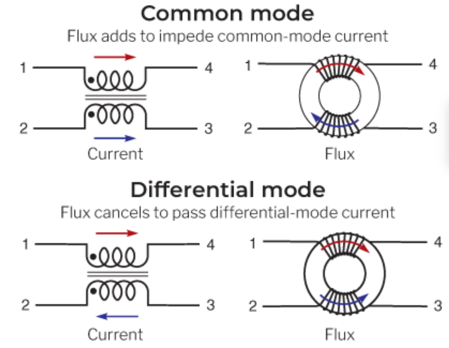
In a CMI, the current in the two lines travels in the same direction, and the combined magnetic flux creates an opposing field that blocks the noise. That contrasts with a differential mode inductor (DMI) where the currents flow in opposite directions, and the flux cancels, so the field does not oppose signal transfer, as shown in Figure 1. Some of the key specifications for CMIs include:

  • Impedance rating is related to the amount of noise attenuation required.
  • The frequency bandwidth of the anticipated noise determines the frequency range.
  • The current rating is determined by the maximum temperature rise allowable for the inductor.
Figure 1. Common mode and differential mode inductors are defined by the relative directions of current flow in the two conductors (Image: Coilcraft).

SPE CDNs
The CDN’s CMI is designed to balance the signal, making it symmetrical and ensuring no common mode noise interferes with the differential mode information. A CMI with a large common mode impedance and small differential mode impedance is required to filter the common mode noise without damaging the integrity of the information carried on the differential signal,

Mode conversion is another consideration when selecting CMIs. The more turns on an inductor with a given winding technology, the higher the mode conversion between differential and common mode. High mode conversion is bad for signal integrity since more of the differential signal is converted into the common mode in some frequency ranges. Return loss, the ratio of the reflected signal to the incident signal, must be minimized in the CMI for best system performance.

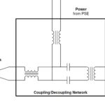
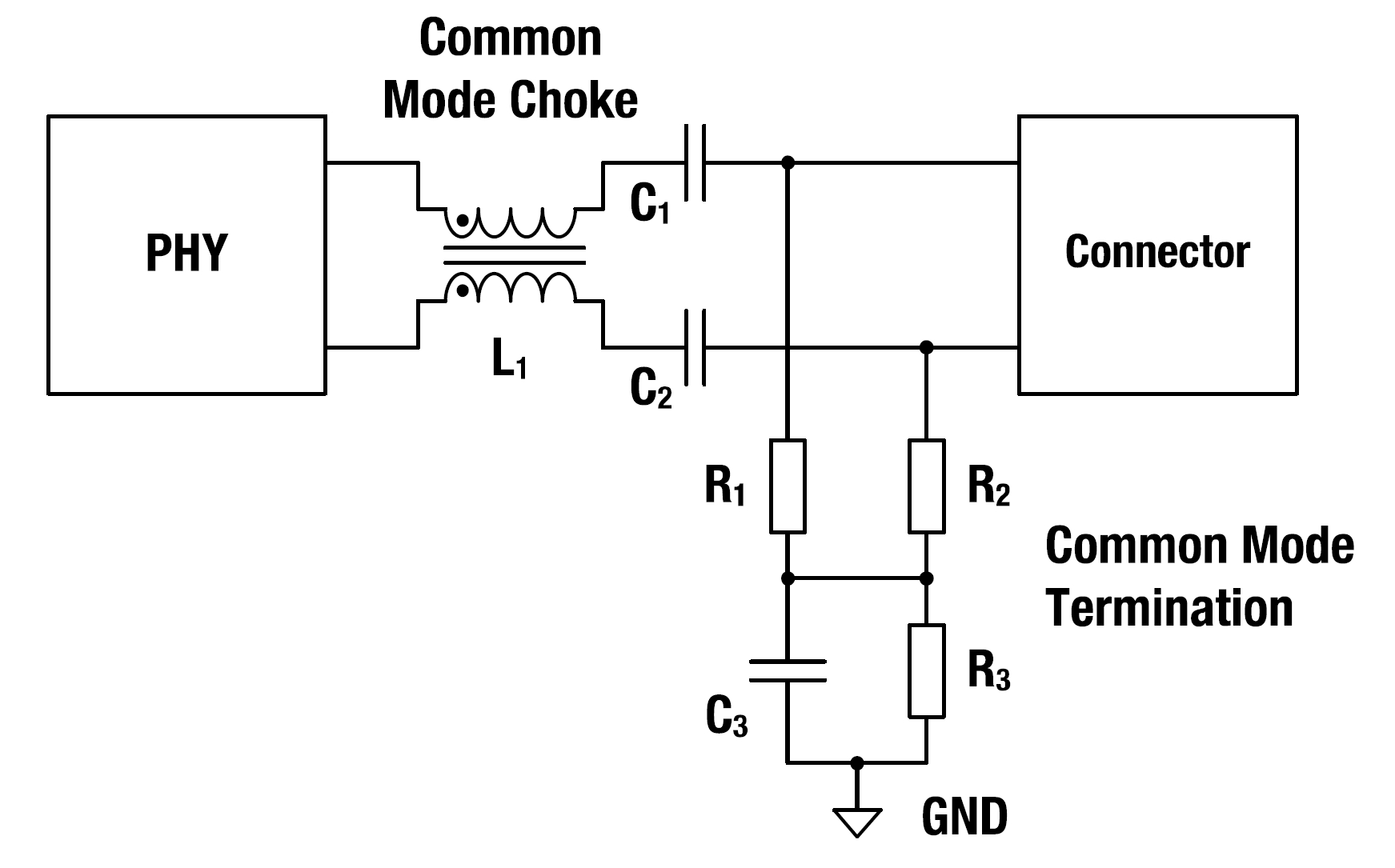
The CMI is a key component in the common mode termination, matching the network to the ground at the connection point between the network cable and the SPE electronics, as shown in Figure 2. The network consists of three resistors and one capacitor. R1 and R2 are typically 1 kΩ and terminate the wires balanced to ground, minimizing interfering common mode signals. Decoupling of direct currents is ensured by C3, a 1000 nF capacitor, and R3, a 100 kΩ discharge resistor. In addition to the termination network, two small capacitors, C1 and C2, typically 100 nF and 50 V, are used with cable lengths of up to 15 meters, as are common in low-voltage designs found in automotive SPE applications.

Figure 2. The CMI (common mode choke) connects the PHY electronics to the connector and SPE cabling (Image: SPE Industrial Partner Network).

Summary
The CMI connects the SPE electronics to the network cabling and protects the data lines from high-frequency noise. Key specifications include impedance, frequency range, and current rating. Mode conversion and return loss are also important performance considerations. The CMI is part of the common mode termination network, which supports robust connectivity.

References
A Guide to Understanding Common Mode Chokes, Coilcraft
Single Pair Ethernet for Industrial Applications, SPE Industrial Partner Network
Single Pair Ethernet: How to implement 10Base-T1L, TDK

You may also like:


  • How to specify differential mode inductors for Single-Pair Ethernet?

  • What is Single-Pair Ethernet and PoDL?

  • August 2023 Issue: Automotive & Transportation Electronics

  • How do MCUs support automotive infotainment systems?

  • How do the seven types of V2X connectivity work?

Filed Under: Ethernet, FAQ, Featured Tagged With: FAQ

Primary Sidebar

Featured Contributions

What’s slowing down Edge AI? It’s not compute, it’s data movement

Five challenges for developing next-generation ADAS and autonomous vehicles

Securing IoT devices against quantum computing risks

RISC-V implementation strategies for certification of safety-critical systems

What’s new with Matter: how Matter 1.4 is reshaping interoperability and energy management

More Featured Contributions

EE TECH TOOLBOX

“ee
Tech Toolbox: EMC/EMI
EE World has assembled a collection of articles that demonstrate how to measure emissions with simple antennas. We include a review of a handheld spectrum analyzer. We also look at EMC issues with IoT devices.

EE Learning Center

EE Learning Center

EE ENGINEERING TRAINING DAYS

engineering
“bills
“microcontroller
EXPAND YOUR KNOWLEDGE AND STAY CONNECTED
Get the latest info on technologies, tools and strategies for EE professionals.

DesignFast

Design Fast Logo
Component Selection Made Simple.

Try it Today
design fast globle

Footer

Microcontroller Tips

EE World Online Network

  • 5G Technology World
  • EE World Online
  • Engineers Garage
  • Analog IC Tips
  • Battery Power Tips
  • Connector Tips
  • DesignFast
  • EDA Board Forums
  • Electro Tech Online Forums
  • EV Engineering
  • Power Electronic Tips
  • Sensor Tips
  • Test and Measurement Tips

Microcontroller Tips

  • Subscribe to our newsletter
  • Advertise with us
  • Contact us
  • About us

Copyright © 2025 · WTWH Media LLC and its licensors. All rights reserved.
The material on this site may not be reproduced, distributed, transmitted, cached or otherwise used, except with the prior written permission of WTWH Media.

Privacy Policy