• Skip to primary navigation
  • Skip to main content
  • Skip to primary sidebar
  • Skip to footer

Microcontroller Tips

Microcontroller engineering resources, new microcontroller products and electronics engineering news

  • Products
    • 8-bit
    • 16-bit
    • 32-bit
    • 64-bit
  • Applications
    • 5G
    • Automotive
    • Connectivity
    • Consumer Electronics
    • EV Engineering
    • Industrial
    • IoT
    • Medical
    • Security
    • Telecommunications
    • Wearables
    • Wireless
  • Learn
    • eBooks / Tech Tips
    • EE Training Days
    • FAQs
    • Learning Center
    • Tech Toolboxes
    • Webinars/Digital Events
  • Resources
    • Design Guide Library
    • DesignFast
    • LEAP Awards
    • Podcasts
    • White Papers
  • Videos
    • EE Videos & Interviews
    • Teardown Videos
  • EE Forums
    • EDABoard.com
    • Electro-Tech-Online.com
  • Engineering Training Days
  • Advertise
  • Subscribe

How’d they do that? Researchers connect 3D-printed sensors to WiFi without using electronics

December 6, 2017 By Lee Teschler 4 Comments

A group of researchers at the University of Washington have figured out a way to make 3D-printed objects emit WiFi signals containing status information, all without using electrical power.

antenna switch
The 3D-printed bow tie antenna. Below, the spring-driven mechanical switch that connects the two halves of the bow tie antenna in the unpressed and pressed position. Teeth on a coded gear press the switch down to make contact with the antenna.
The technique uses what’s called WiFi backscattering. The method is to make the 3D-printed device amplitude-modulate a WiFi signal coming from a conventional source such as a wireless router. Then a separate receiver is used to detect the amplitude modulation pattern that the 3D-printed device superimposes on the WiFi emissions.

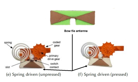
Researchers implemented the backscattering idea by 3D-printing a WiFi antenna, then connecting and disconnecting it as a way to reflect and not-reflect the WiFi signal to form a coded pattern. Then a receiver — they used a MAX2829 802.11a/b/g transceiver — decodes the backscatter information from the amplitude variations in the received Wi-Fi signal across packets.

3D printed code gears
The drive gear (left) and two types of coded gears, one where the presence and absence of teeth signal 1s and 0s, a second where teeth with an extended width signal 1s in a way analogous to Morse code.
To make the scheme work without using electrical power, the researchers came up with a mechanical means of breaking and making connections to the 3D-printed antenna in a way such that a broken connection would drastically detune it. Thus the antenna would reflect WiFi signals when connected, not reflect when disconnected. To accomplish this, they devised a 3D-printed bowtie type antenna with a 2-mm gap at the center. A mechanical switch either connects or disconnects the two halves.

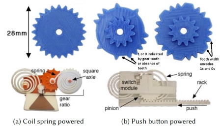
To generate a digital code without using external power, the group devised a spring-actuated switch actuated by a coded gear. When a gear tooth pressed down on the switch, it would make a connection between the two halves of the bow tie antenna. They tried two kinds of coding schemes: one where the presence of a gear tooth indicated a 1 bit and the absence of a tooth indicated a 0 bit, and a second where a gear encoded 1s and 0s by doubling the tooth width in a manner analogous to Morse code.

Researchers tried several kinds of springs but got good results using a planar coil spring orthogonal to the contact surface. A slot guides the contact to ensure it stays parallel to the contact surface. The coded gear couples to a 3D-printed, tightly coiled planar spring where the outer edge of the spring is held at a fixed point, and the center couples to a gear using a square axle.

The spring gets wound up to “charge” the device, then applies torque to the square axle and therefore to the connected gear as it unwinds. The gear to which the coil spring attaches, in turn, actuates a circular gear with the encoded bits. By controlling the ratio between the size of the primary and circular gears, researchers control the speed at which the switch toggles between the two states.

Application demos of the 3D printed WiFi sensors: As an anemometer to measure wind speed, a flowmeter to measure water flow, and a weight scale.
In operation, the device would backscatter a WiFi signal when something turned the gear — in one demonstration an anemometer turned it as a way of recording wind speed. Researchers have tried their apparatus and detected the backscatter effect it generates over a distance of 15 cm using a WiFi source as far away as about 16 m. The bit rates involved are, of course, relatively slow, ranging from 16 to 45 bps.

The researchers described their work at the recent ACM Siggraph Conference and Exhibition on Computer Graphics and Interactive Techniques in Asia.

You may also like:


  • The IoT and motion control fuels a rising tide of…

  • Top microcontroller threads on EDAboard.com — January

  • Teardown: Does the Amazon Dash set the tone for IoT…

Filed Under: Applications, Connectivity, Featured, Wireless

Reader Interactions

Comments

  1. Wolfgang Schechinger says

    December 8, 2017 at 3:44 am

    What is absolutely missing in this paper is, how the backscatter information actually was extracted from the MAX2829 chip. The diagrams in the paper give no information about time scale or frequency ranges, also the text does not and leaves everything open to guesses.

    Does one need to assume that sophisticated and expensive laboratory equipment, capable of performing signal analysis in the GHz range is required, and that the task is not able to be accomplished with hardware that is equivalent to the low-end 3D printing equipment that is advertised to make the backscatter gadgets so attractive to the outside world (namely , i.e. by using small scale, affordable and easy to program micro controllers like Arduino or ESP32?)

    In effect, the referenced commercial WiFI routers need to modified, be it on the hardware level or by using additional software. In my humble opinion, this missing information is a crucial requirement for a scientific publication.

    As a scientific reviewer, I would not have accepted the paper in this form for publication.

    Reply
    • Lee Teschler says

      December 8, 2017 at 8:44 am

      I think the key here is this passage from the Siggraph paper: “In our case, the backscatter signal is a narrowband transmission embedded on top of the ambient Wi-Fi signals, since the printed Wi-Fi objects send data at a low data rate. The Wi-Fi receiver can extract this information by tracking the amplitude of Wi-Fi signals across multiple packets. Specifically, we normalize the received Wi-Fi signals across packets on a scale of +1 to -1 and apply a 10th order 100 Hz low pass filter. This filters out the high frequency information in the Wi-Fi signal leaving the backscatter data. Our filter parameters are chosen to minimize noise at bitrates up to 45bps, which is a standard technique in communications. Additionally, our filter bandwidth minimizes the amount of high frequency noise. The resultant data can then be processed for sensing by mapping the sensor value to the rate at which bits are backscattered by the sensor….”
      If I understand this correctly, they are just applying some kind of envelope detector to the received reflected WiFi signal. No modification of the WiFi router would be necessary.

      Reply
      • ThreepE0 says

        March 31, 2021 at 9:32 pm

        I know this is an old comment, but I figure it might be worth asking:

        Does this setup not require a dedicated transmitter? The way I read the paper, I was think there was a transmitter that sent a constant known signal, and the buttons and devices overlayed their backscatter data on top of that. The difference in the known signal and what would be received by a client would be the end signal.

        If this isn’t the case, and there isn’t a known given signal, how can they distinguish between noise/interference/arbitrary wifi and backscatter data?

        Reply
  2. Nick Carter says

    August 19, 2021 at 12:54 pm

    This is Amplitude Modulation. They use a WiFi receiver and monitor the received signal strength. They then calculate the variations of that number over time in reference to the “baseline” level. They filter those variations so that only the signal variation at the rate they want (45 bits/sec) is left. Their WiFi signal is up to 16M away but the range at which they can detect the variations they induce is really low 16 cm.
    With such a low detection distance, I am not sure of the real benefit, unless they can find a detector that required no work, Otherwise they have to build and program the detector.
    They could just as well have used a mirror to modulate light reflection from the printed device, and a longer range than 16 cm I would expect.
    But it is a fun project anyway.

    Reply

Leave a Reply Cancel reply

Your email address will not be published. Required fields are marked *

Primary Sidebar

Featured Contributions

Five challenges for developing next-generation ADAS and autonomous vehicles

Securing IoT devices against quantum computing risks

RISC-V implementation strategies for certification of safety-critical systems

What’s new with Matter: how Matter 1.4 is reshaping interoperability and energy management

Edge AI: Revolutionizing real-time data processing and automation

More Featured Contributions

EE TECH TOOLBOX

“ee
Tech Toolbox: Internet of Things
Explore practical strategies for minimizing attack surfaces, managing memory efficiently, and securing firmware. Download now to ensure your IoT implementations remain secure, efficient, and future-ready.

EE Learning Center

EE Learning Center

EE ENGINEERING TRAINING DAYS

engineering
“bills
“microcontroller
EXPAND YOUR KNOWLEDGE AND STAY CONNECTED
Get the latest info on technologies, tools and strategies for EE professionals.

RSS Current EDABoard.com discussions

  • CST Studio – How to increase frequency step size (e.g. to 100 MHz)?
  • What is the difference between MIMO antenna elements arragned radially across the pentagon shaped substrate versus rectangle shaed substrate?
  • General purpose CMOS Op Amp and PMOS & NMOS from LTSpice library
  • Simple Active Bandpass Filter Oscillates
  • TMP117 > Can not read temperature on LCD

RSS Current Electro-Tech-Online.com Discussions

  • Capacitive Touch On The Profile
  • JBL charge 4 dead motherboard?
  • Guitar electronics project
  • can a AT89C51 be used as a rom?
  • going out on a limb and praying the schematic is correct

DesignFast

Design Fast Logo
Component Selection Made Simple.

Try it Today
design fast globle

Footer

Microcontroller Tips

EE World Online Network

  • 5G Technology World
  • EE World Online
  • Engineers Garage
  • Analog IC Tips
  • Battery Power Tips
  • Connector Tips
  • DesignFast
  • EDA Board Forums
  • Electro Tech Online Forums
  • EV Engineering
  • Power Electronic Tips
  • Sensor Tips
  • Test and Measurement Tips

Microcontroller Tips

  • Subscribe to our newsletter
  • Advertise with us
  • Contact us
  • About us

Copyright © 2025 · WTWH Media LLC and its licensors. All rights reserved.
The material on this site may not be reproduced, distributed, transmitted, cached or otherwise used, except with the prior written permission of WTWH Media.

Privacy Policy