by Bill Cheung, Orient Display
The LCD has been widely used in different applications, such as automotive, home appliance, medical, industrial, communication, entertainment, consumer devices, etc. It has been the most popular display technology for more than a decade after surpassing CRT. But the LCD has its genetic drawbacks, such as narrow viewing angle, slow response, and low contrast, limiting its use in some applications. These drawbacks also make LCDs venerable for other new display technologies, OLED (Organic Light Emitting Diode) and Micro LED. Engineers have been working on different ways to improve the LCD drawbacks. Today, we will discuss the LCD contrast affected by temperature and improve LCD contrast with the temperature changes.
How LCD works?
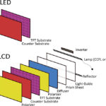
A most simple TN (Twisted Nematic) panel contains two polarizers, two glass substrates with transparent electrodes, ITO (Indium Tin Oxide), and a thin liquid crystal material layer sandwiched between the electrodes. See Figure 1.
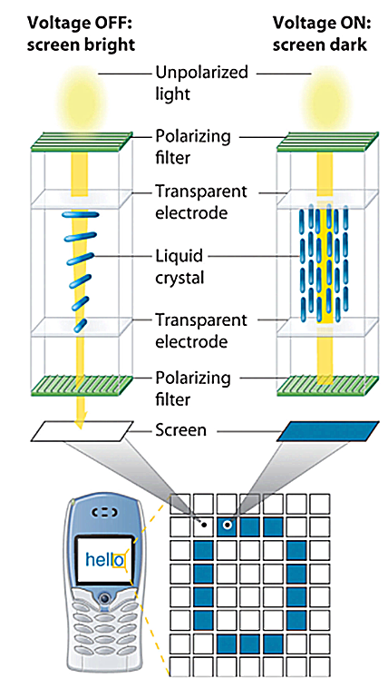
When the voltage is off, the light source’s natural light goes through the top polarizer to become polarized linear light. When it meets with nematic liquid crystal molecules, it twists with the liquid crystal twist layer. After twisting 90o, it passes through the bottom glass and arrives at the bottom polarizer. As the polarized light is in a parallel position with the bottom polarizer, it goes through a polarizer, and we can see the light (white or grey pixel). When the voltage is on, the liquid crystal molecular will be perpendicular to the glass surface and lose its twist under the electric field. When the polarized light meets the nematic liquid crystal layer, it keeps the original transmissive without twisting. The bottom polarizer will be blocked as the linear light and bottom polarizer are in a perpendicular position. We do see the light (black pixel).
Liquid Crystal Material Threshold Voltage (V90)
V10 is the voltage at 10% of the transmission level; it is also named the saturation voltage (Vsat).
V90 is the voltage at 90% of the transmission level; it is also named the threshold voltage (Vth).
The ratio V10/V90 is defined as sharpness or steepness. It reflects how many multiplexes the LCD can be used.
Figure 2 shows that V10>V90 is a positive display, while V90>V10 is a negative display.
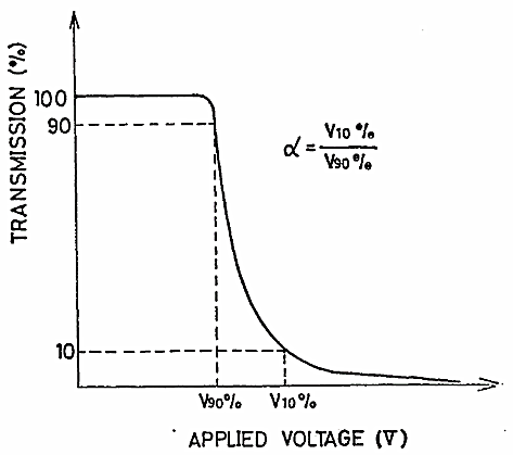
From Figure 2, when the voltage increases, the LCD’s transmission is getting lower. When the transmission level reaches 90% of the no voltage applied, we can see the LCD shows images but very light. We call it the threshold voltage (V90 or Vth).
LCD voltage vs temperature
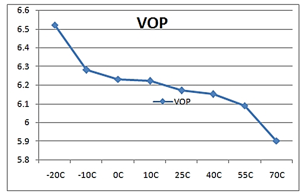
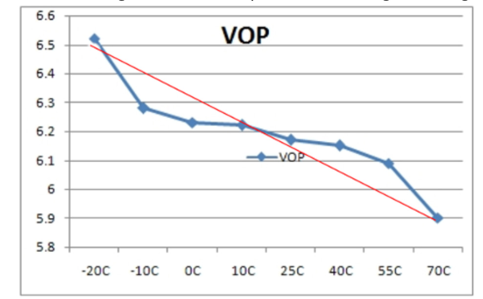
Please see Figure 3 for LCD operating voltage (Vop) change with temperature we measured from our electro-optical lab.
From Figure 3, we can see the LCD voltage decreases with the temperature. From -15oC to +60oC, the curve relatively flat, but when the temperature is lower than -20oC and higher than +70oC, the voltage changes dramatically with temperature, that is why most LCD has an operating temperature of -20 oC to +70 oC. Some LCD manufacturers stated that the LCD has an operating temperature range of -30 oC to +80 oC, but be ready that the poor contrast has to be accepted with both ends of the temperature.
LCD contrast vs. temperature
Please refer to Figure 4 for what we measured in our lab for LCD contrast changes with temperature.
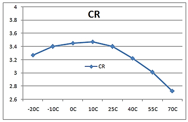
From Figure 4, we can see the LCD contrast is optimized at a temperature of around +20oC, which is room temperature. The contrast (CR) decreases with higher and lower temperatures, which can be a big issue for some applications.
Ways to improve LCD contrast under low and high temperatures
Scientists and Engineers of different areas have been trying to improve the LCD contrast under low and high temperatures. But the facts are all of them having trade-off. The users have to balance all the factors to choose the best solutions for their applications. We will explain the most popular ways for LCD to deal with temperature.
- Improve LCD contrast under high temperature ONLY
It is easier to do. The contrast dramatically changes at a higher temperature because liquid crystal material is close to its clearing point. The material in the LCD is no longer liquid crystal material anymore; it becomes liquid (like water). Then, the solution will be to increase the clearing point of the material used. Most commercial LCDs use liquid crystal material with a clearing point of around 80oC, making it useable at +70oC. Still, for those conditions, the liquid crystal material used as a clearing point closer to 130 oC makes it useable over +100 oC theoretically.
Of course, we can imagine that material is costly. Another issue that the high-temperature performance LCDs have a bad performance at low temperature. The response time at low temperatures can be very long.
- Improve LCD contrast under low temperature ONLY
The heater can be used to heat LCD when the temperature drops below -20 oC. Of course, the temperature sensor can be used to switch on/off the heating. Usually, there are 3 kinds of heaters to be used. 1) wire heater, 2) ITO heater on flex, 3) ITO heater on the glass. Depending on the heating speed needed, the heating power can be designed.
Of course, you can see the issue of using a heater in an LCD. The first is the cost; the second is the power of heating. Please prepare to use around 1 to 2w/inch2 power budget in your design.
- Flat fluids
The biggest liquid crystal material manufacturer in the world, E. Merck claimed that they developed “Flat Fluids,” which makes the curve in Figure 3 LCD Operating Voltage (Vop) vs Temperature relatively flat from -30 oC to +80 oC. It is good news for most applications. But the limitation is that Flat Fluids can only be used in TN-type displays also costly.
- Temperature compensation circuitry
In the past, engineers designed temperature compensation circuitry shown in the example in Figure 5.
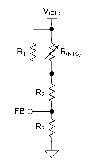
The good news that many modern LCD controllers include temperature compensation circuitry in the IC design, dramatically makes the design work easier by simply setting the function. But all the LCD temperature compensation circuitry is linear, which can’t match the liquid crystal material voltage curve with temperature. But it is good enough for most applications. See Figure 6.
About the author
Bill Cheung is an engineering lead and marketing manager at Orient Display.
Leave a Reply