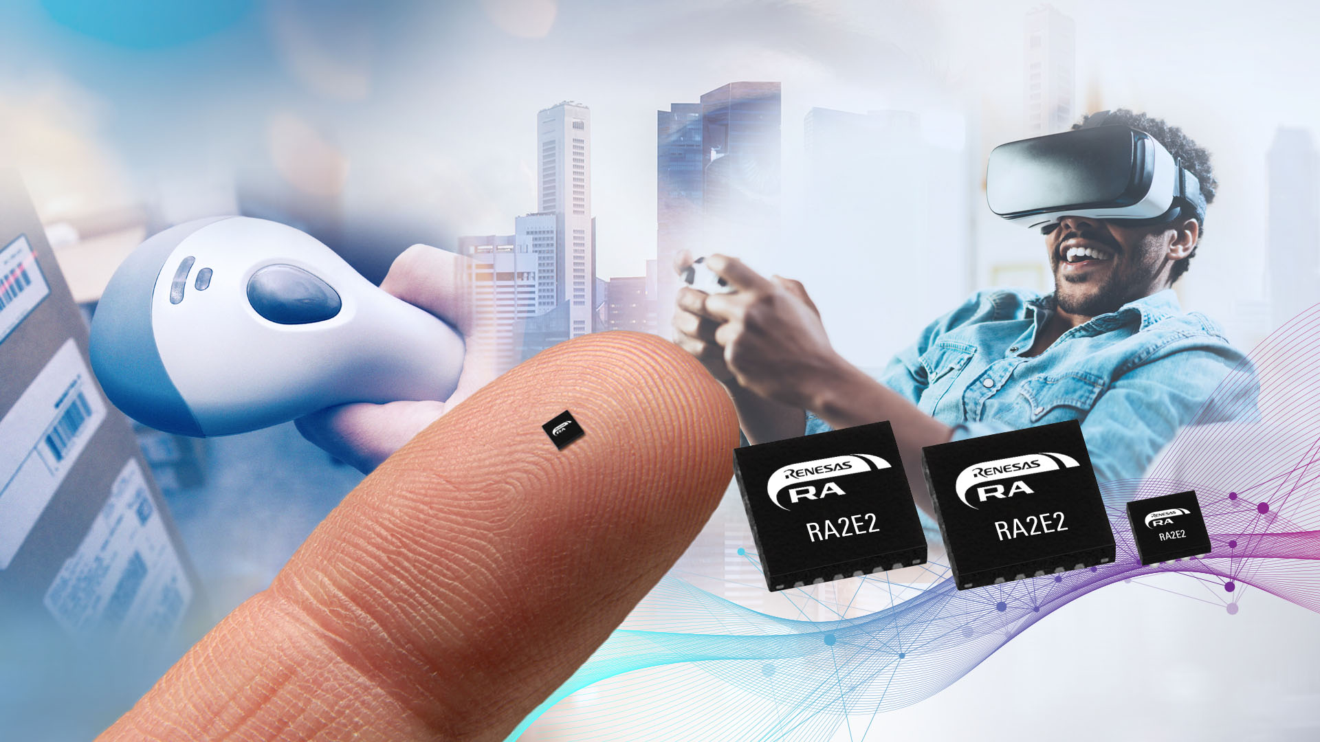
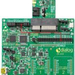
The optimization of microcontrollers (MCUs) in power-sensitive applications such as wireless sensor nodes and wearables is all about maximizing power management effectiveness. To minimize power consumption, low-power MCUs typically operate at frequencies below 50 MHz, compared with hundreds of MHz or even 1+ GHz for conventional MCUs. These power-optimized MCUs also use low-power peripherals; they can have complex sleep modes, complex multiprotocol wireless communications implementations, and specialized peripherals such as wake-up receiver and sensor controllers, which are not found in their high-performance and less power-sensitive cousins. They are often packaged in smaller formats with lower pin counts. For example, a recent 32-bit MCU optimized for IoT applications such as wearables, medical devices, sensor nodes, and industrial automation operates at 48-MHz and is offered in a 16-pin wafer level chip scale package (WLCSP) measuring 1.87 mm square and 0.4 mm thick (Figure 1).
Energy-optimized 32-bit MCUs are available that consume less than 200 μA/MHz in active mode with standby currents under 400nA in sleep mode. Energy-optimized MCUs for IoT sensors and wearables can offer a variety of space-saving peripherals such as SenseWire (I3C) communication interfaces, on-chip precision oscillators, true random number generators (TRNGs), cryptographic accelerators, temperature sensors, and more.
Power management functions in low-power MCUs and associated wireless transceivers are optimized to deliver the maximum battery life given the large and rapid changes in power consumption when switching between sleep and active modes (Figure 2). As a result, it’s now possible to power some wireless sensor nodes and similar low-power devices using energy harvesting. One key to minimizing power consumption in these devices is maximizing the relative time spent in sleep mode. The MCU can wake up and perform all the needed functions quickly with an equally quick return to sleep, minimizing the duration of peak power consumption, minimizing overall power consumption through the overall wireless node power cycle.
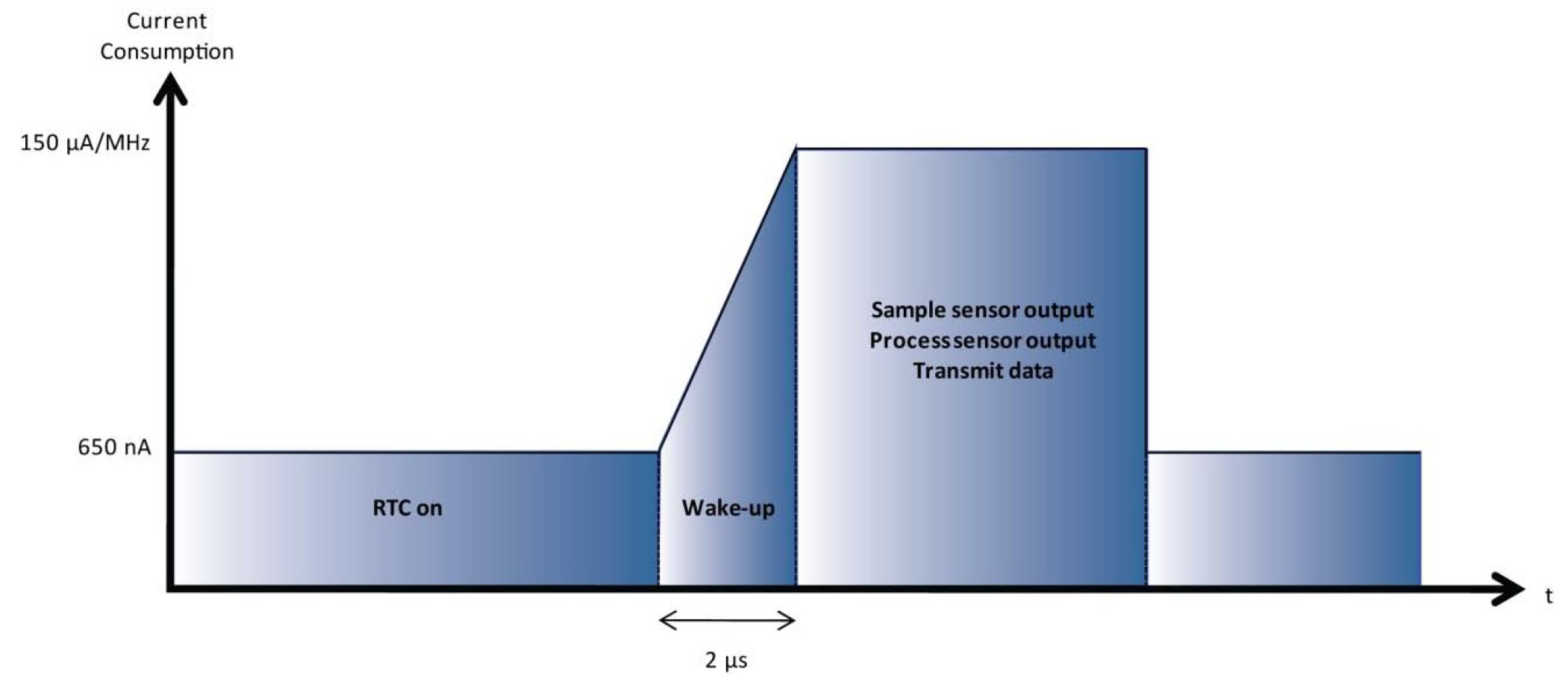
Optimization of energy consumption in sleep mode is critical to minimization of power consumption in wireless sensor nodes. And, since the real-time clock (RTC) is often the only subsystem that stays on during sleep mode, optimization of RTC power consumption is a key consideration. In MCUs designed for use in wireless sensor nodes, the RTC typically consumes a few hundred nanoamps. In addition to minimizing RTC power consumption, it’s critical to properly manage the wake-up function, sensor polling, and subsequent data transmission activities.
Wireless sensor nodes need to wake up to measure a sensor signal. That measurement is often implemented using an analog-to-digital converter (ADC). A properly designed wake-up function matches the wake-up time of the MCU to the wake-up time of the ADC. If the MCU wakes up too fast before the ADC is functioning, precious energy can be wasted. The frequency of waking up the system is also an important consideration. The RTC typically operates as a free-running counter. For example, if a 32.768 kHz crystal is used, a 16-bit free-running counter generates an interrupt every two seconds that wakes up the MCU. Replacing the 16-bit counter with a 32-bit counter will generate the wake-up interrupt less frequently and save energy, with the possible tradeoff of less frequent sensor measurements.
Optimization of the wireless communication subsystem is another important consideration. Minimizing the time needed to transmit data by avoiding complicated communications protocols can lower power consumption. A low-power ISM band radio may need less than 30mA for one or two milliseconds to transmit sensor data. If the sensor node is expected to respond to external requests for measurements, the problem is more complicated, and the MCU may be needed to manage the radio(s) directly.
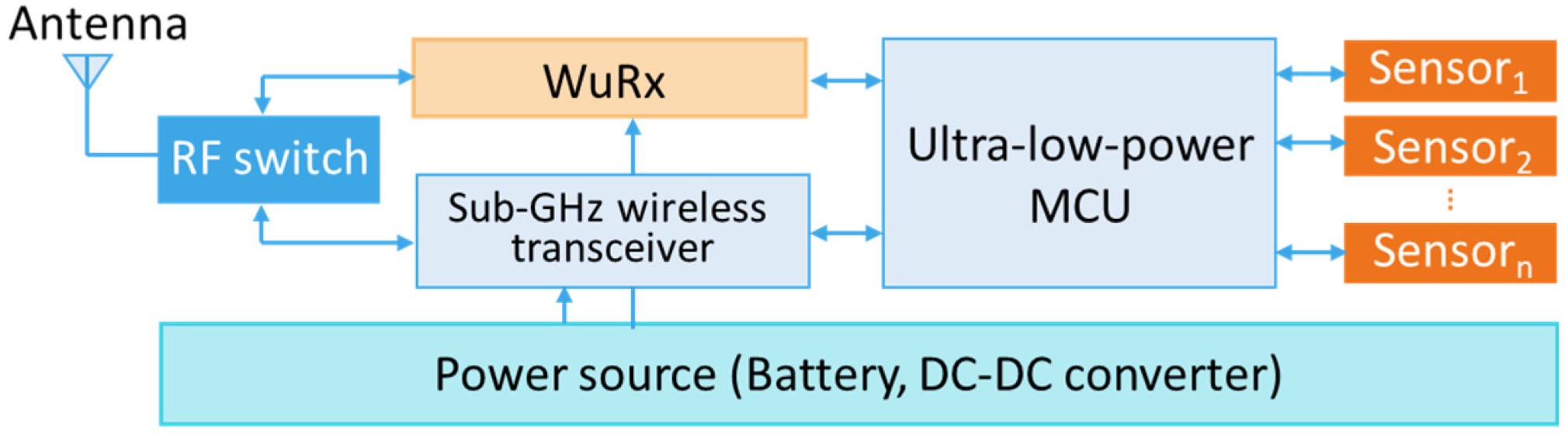
If the main receiver is not completely switched off during sleep mode, it can consume significant power and potentially increase latency. Using a separate wake-up receiver (WuRx) optimized for ultra-low power consumption can provide an alternative communications architecture (Figure 3). A properly implemented WuRx can support always-on listening capability while consuming only a few µW. The WuRx is used in addition to the main radio. Once the WuRx receives a wake-up request, it wakes up the MCU, which in turn wakes up the peripherals (such as ADCs) and the main radio.
Multiprotocol wireless communications
While controlling radio power consumption is important for extending battery life, the utility of wireless devices can be increased with multiprotocol connectivity. Bluetooth can enable smartphones to control wireless devices, Zigbee and Thread can make it possible to control devices remotely through a gateway. The combination of sub-GHz and Bluetooth communication in IoT devices can simplify setup, maintenance, and information collection from devices such as smart meters and smart appliances. The recent emergence of mioty compliments other sub-GHz LPWAN communications protocols such as LoRaWAN and Sigfox.
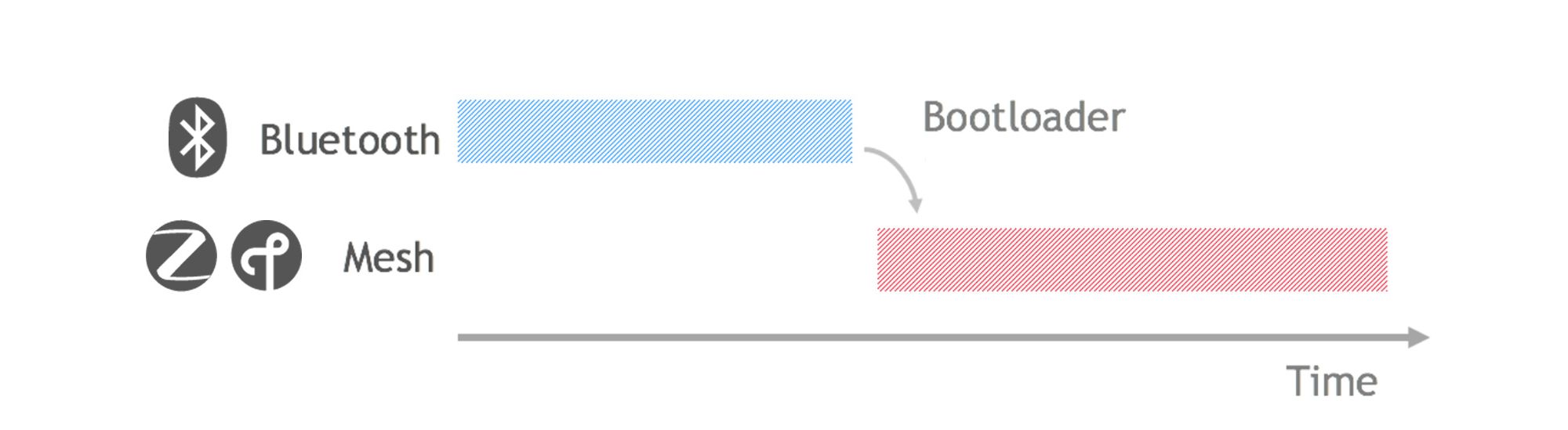
Switched multiprotocol implementations enable a device to switch between several wireless protocols (Figure 4). Switching between Bluetooth and various mesh protocols such as Zigbee or Thread can significantly enhance the utility of wireless IoT devices and wearables. An MCU that supports over-the-air updates can further enhance performance by enabling updates to new or improved communications protocols as they become available.
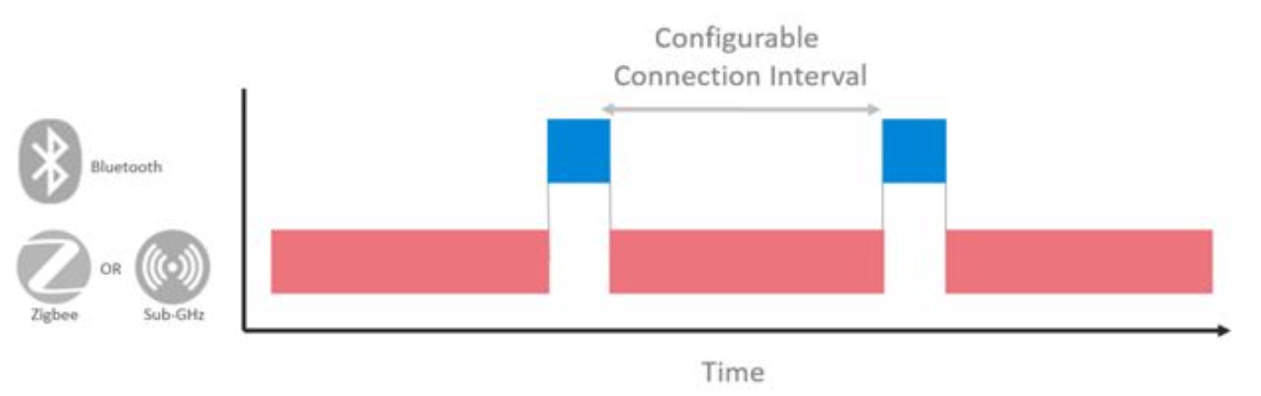
It’s possible to implement dynamic multiprotocol communications architectures under the control of the MCU (Figure 5). When appropriate, dynamic multiprotocol implementations can use time-slicing techniques to enable multiple protocols to share a single radio. A simple example is adding Bluetooth to a device that uses Zigbee, Thread, or a sub-GHz wireless protocol.
Operation of multiple protocols using multiple radios dedicated to specific frequencies can be more efficient but costs more and takes up more space. For example, a home area network can include both 2.4 GHz Zigbee devices and sub-GHz (868 MHz) Zigbee devices with the communications hub routing traffic between devices on different radio frequencies operating under control of the MCU.
MCUs plus sensor controllers
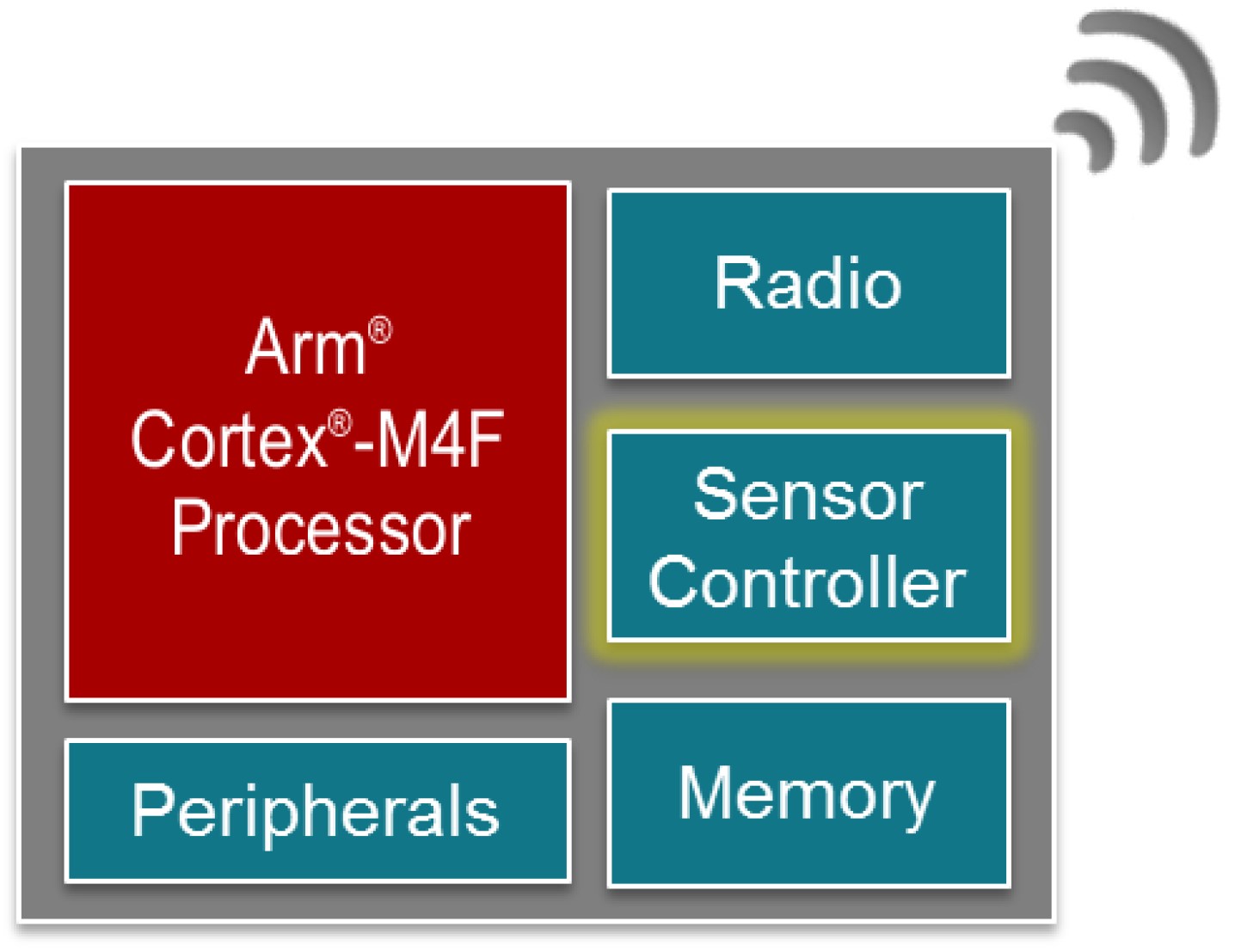
The addition of a sensor controller serves a similar function for sensor measurements that a WuRx performs for wireless communications. While the main MCU is typically a 32-bit device, a sensor controller is a lower-power 16-bit core optimized for very low power and runs independently from the main MCU (Figure 6). Just as a WuRx enables the main radio to stay in sleep mode for as long as possible, the sensor controller enables the main MCU to sleep longer, waking up only to perform compute-intensive tasks.
A sensor controller typically operates in an auxiliary power and clock domain, separate from the main MCU. It’s designed to implement background tasks such as:
- Polling analog and digital sensors
- Simple waveform generation for LCDs or other devices.
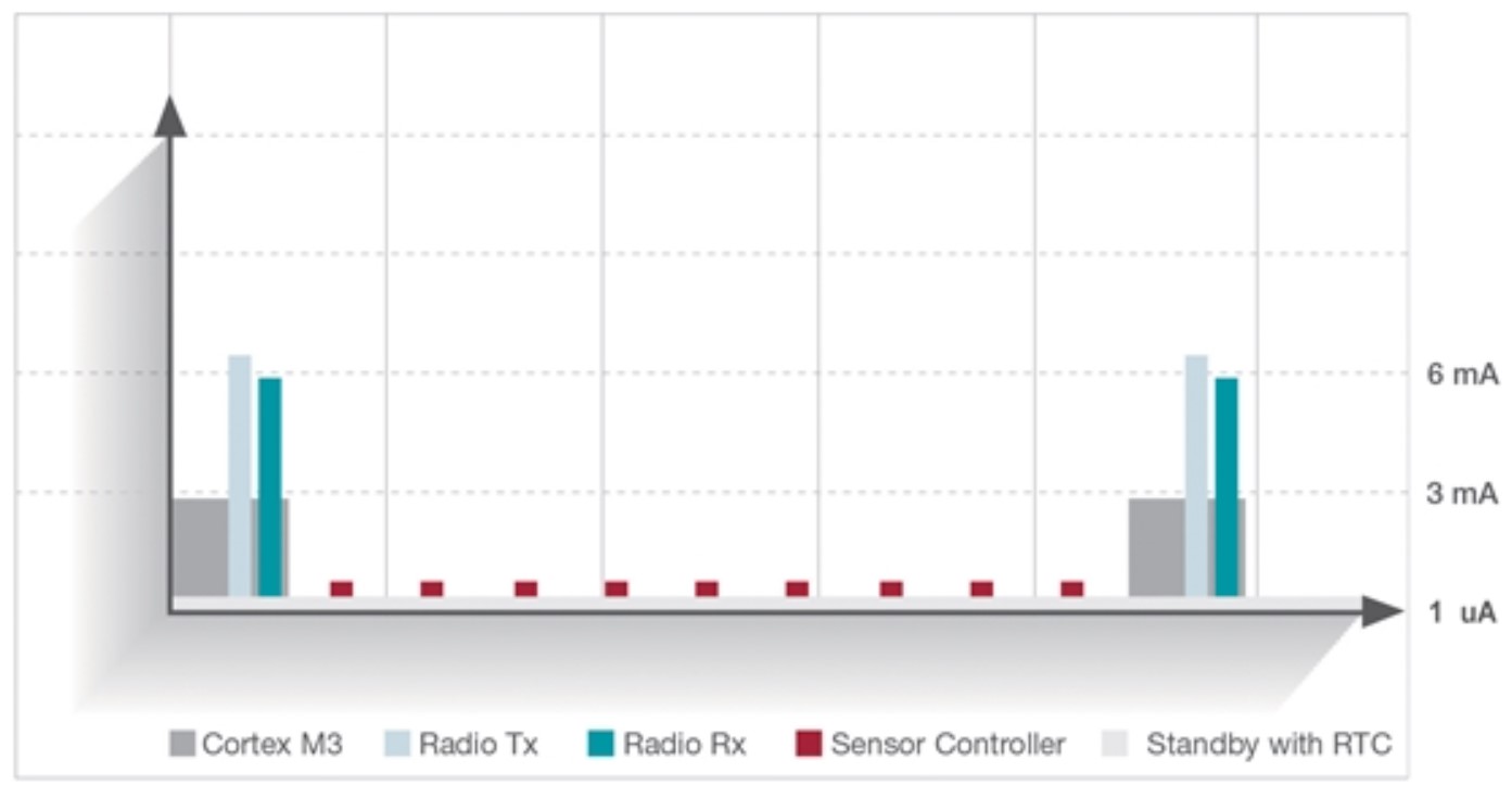
Sensor controllers can efficiently implement simple tasks that may need to be run with higher duty cycles than communications or other energy-intensive functions (Figure 7). The use of a sensor controller can also increase system flexibility. For example, a heart-rate monitor may need to capture sensor data 10 times per second to capture the heart rate accurately. A sensor controller can poll the sensor using an ADC and wake up the main MCU relatively infrequently as sufficient data is captured for further processing. The sensor controller can also vary the duty cycle as directed by the main MCU based on sensor data analysis. For example, an unstable heart rate may require more frequent monitoring. The wireless transmission of the heart rate data can be separately controlled with its duty cycle, further minimizing energy consumption.
Summary
There are many paths to maximizing MCU performance and minimizing energy consumption in wireless sensor nodes and wearables. In addition to specifying an energy-optimized MCU, designers have several tools to maximize the performance for specific application needs. Those tools include optimization of the RTC function and the sleep time profile of the system, integration of energy-efficient wireless communication using WuRx devices and dynamic multiprotocol communications, and the use of dedicated sensor controllers to separate the sensor measurement duty cycle from the general system and radio duty cycles.
References
Energy-Aware System Design for Autonomous Wireless Sensor Nodes: A Comprehensive Review, MDPI Sensors
The Energy Harvesting Tipping Point for Wireless Sensor Applications, Silicon Laboratories
Maintaining Flexibility with Multiprotocol Wireless Connectivity, Silicon Laboratories
Ultra-Low Power Designs With the CC13x2 and CC26x2 Sensor Controller, Texas Instruments

Leave a Reply