
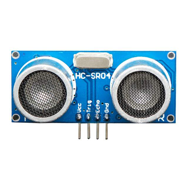
The ultrasonic sensor (or transducer) works on the same principles as a radar system. An ultrasonic sensor can convert electrical energy into acoustic waves and vice versa. The acoustic wave signal is an ultrasonic wave traveling at a frequency above 18kHz. The famous HC SR04 ultrasonic sensor generates ultrasonic waves at 40kHz frequency.
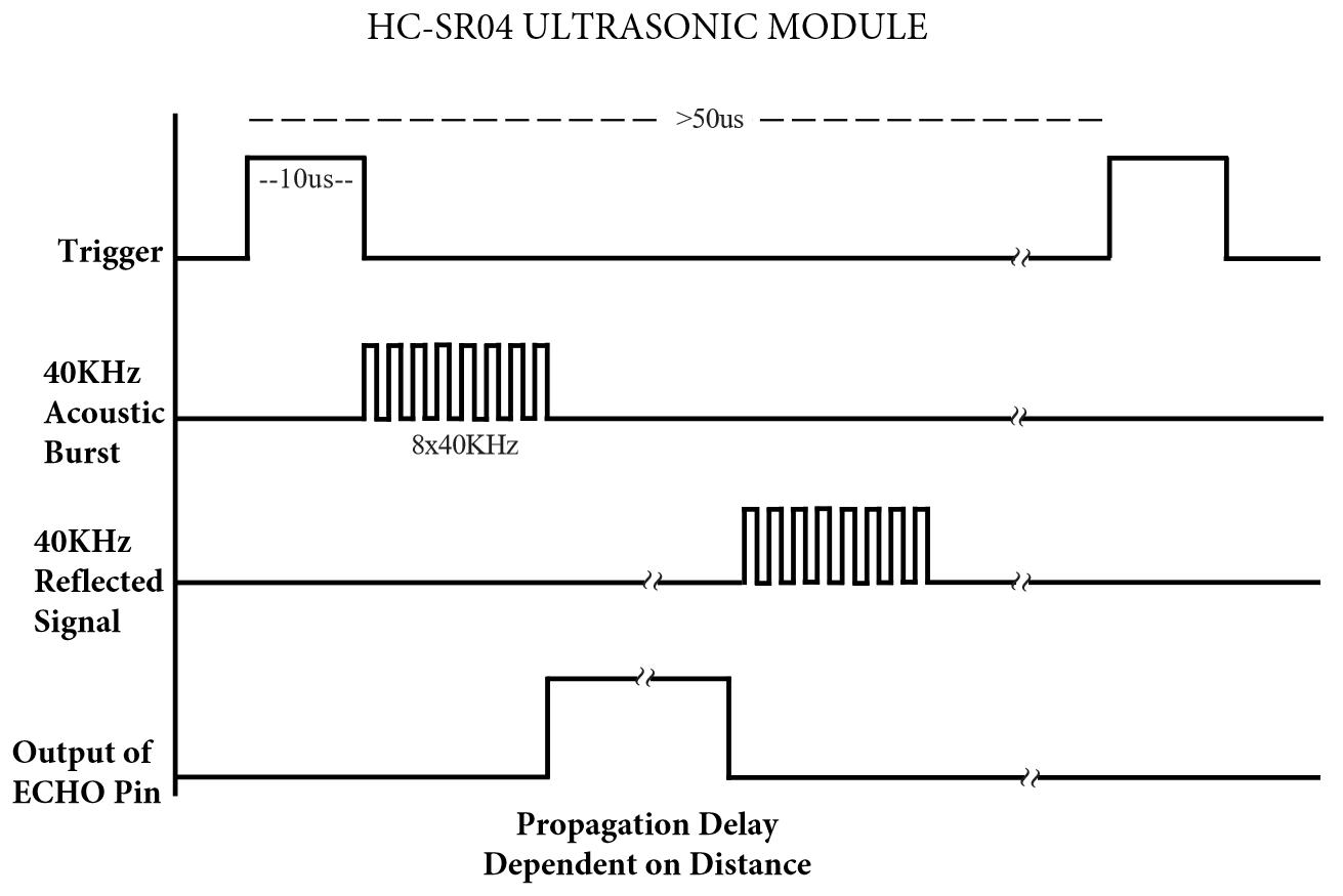
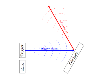
Typically, a microcontroller is used for communication with an ultrasonic sensor. To begin measuring the distance, the microcontroller sends a trigger signal to the ultrasonic sensor. The duty cycle of this trigger signal is 10µS for the HC-SR04 ultrasonic sensor. When triggered, the ultrasonic sensor generates eight acoustic (ultrasonic) wave bursts and initiates a time counter. As soon as the reflected (echo) signal is received, the timer stops. The output of the ultrasonic sensor is a high pulse with the same duration as the time difference between transmitted ultrasonic bursts and the received echo signal.
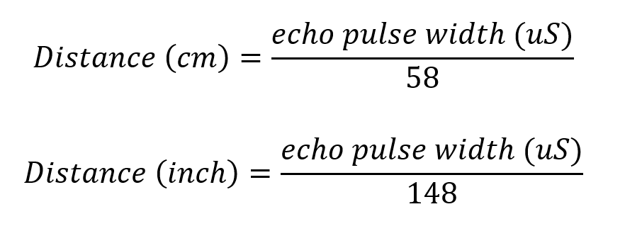
The microcontroller interprets the time signal into distance using the following functions:
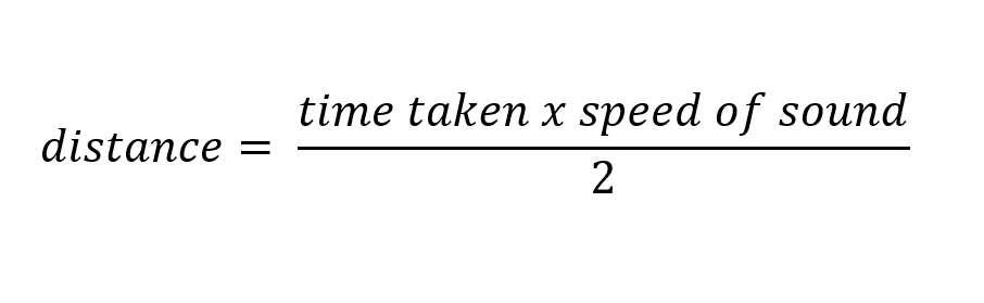
Theoretically, the distance can be calculated using the TRD (time/rate/distance) measurement formula. Since the calculated distance is the distance traveled from the ultrasonic transducer to the object—and back to the transducer—it is a two-way trip. By dividing this distance by 2, you can determine the actual distance from the transducer to the object. Ultrasonic waves travel at the speed of sound (343 m/s at 20°C). The distance between the object and the sensor is half of the distance traveled by the sound wave.[iv] The following equation calculates the distance to an object placed in front of an ultrasonic sensor:
Applications
Multiple areas of engineering use ultrasonic sensors. “No-contact” distance measuring is very useful in automation, robotics, and instrumentation. Below, we investigate the applications of ultrasonic sensors:
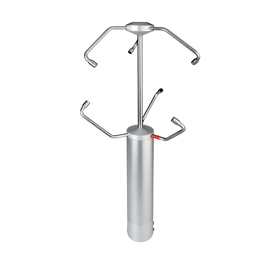
Ultrasonic Anemometers
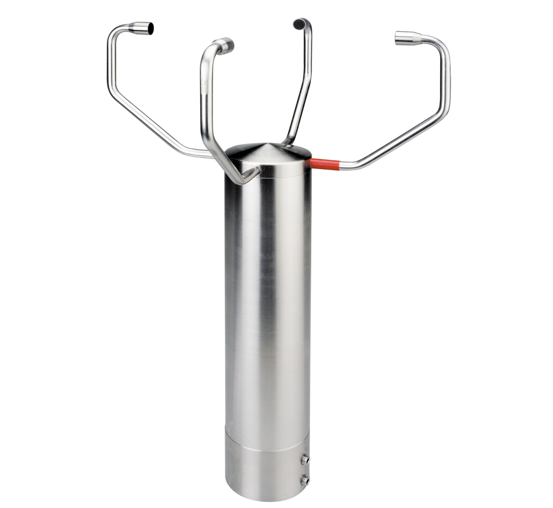
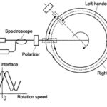
Weather stations commonly used anemometers since they detect wind speed and direction efficiently. The 2D anemometers can measure only the horizontal component of wind speed and direction, whereas 3D anemometers can measure the vertical component of wind, as well.
Apart from measuring wind speed and direction, ultrasonic anemometers can also measure temperature because the speed of ultrasonic sound waves is affected by variations in temperature while maintaining independence from changes in pressure. Temperature is calculated by measuring speed variations in ultrasonic sound.
The ultrasonic anemometer is more durable as compared to the cup anemometer and vane anemometer since it has no moving parts and it operates using ultrasonic sound waves. [vi]
Tide gauge
A tide gauge is used to monitor sea level. It also detects tides, storm surges, tsunamis, swells, and other coastal processes. [vii] A tide gauge can use an ultrasonic sensor to detect real-time water level. The gauge is often linked to an online database where a record is maintained, and in case of a risky situation, the system can trigger an alarm.
Tank level
Measuring fluid level in a tank is similar to a tide gauge. However, in this case, the fluid can be clear water, a corrosive chemical, or a flammable fluid. Unlike optical sensors and float switches, ultrasonic sensors are less likely to corrode as they do not make contact with the fluid.
Functional in sunlight
The sunlight at Earth’s surface is composed of around 52-55% of infrared light.[ix] If an infrared sensor detects an object using infrared light, the process is disturbed due to the interference of infrared light present in sunlight. However, ultrasonic sensors are not affected by the infrared spectrum present in sunlight.
Web-guiding systems
Web-guiding systems position flat materials (e.g., newspaper, plastic film) and widely use ultrasonic sensors. According to Maxcess, “In 1939, Irwin Fife invented the first web guide in his Garage in Oklahoma City, Oklahoma, solving a newspaper owner’s challenge of keeping paper aligned in his high-speed newspaper press.“ [x] A web-guiding system uses a non-contact sensor for detecting and tracking objects at multiple stages. The purpose is to ensure that the material is positioned correctly. If the material is moving out of alignment, the system mechanically places it back on the machine’s processing path. Ultrasonic sensors are suitable for web-guiding systems as the process requires non-contact, high-speed, and efficient functionality.
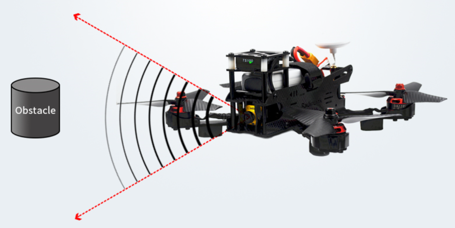
UAV navigation
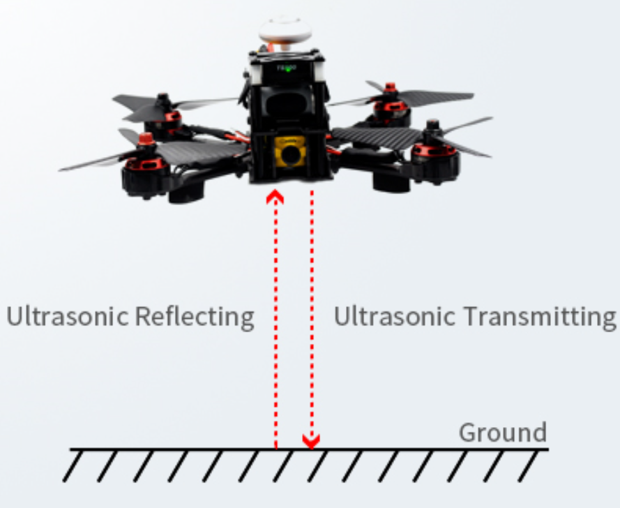
Unmanned aerial vehicles (UAVs)—or drones—commonly use ultrasonic sensors for monitoring any objects in the UAV’s path and distance from the ground.
The autonomous feature of detecting safe distances enables the aircraft to avoid crashing. And as the flight of path changes instantaneously, the ultrasonic detection of distances can prenvent a drone from crashing.
Limitations of ultrasonic sensors
Ultrasonic sensors such as the HC-SR04 can efficiently measure distances up to 400 cm with a slight tolerance of 3 mm. [xiii] However, if a target object is positioned such that the ultrasonic signal is deflected away rather than reflected back to the ultrasonic sensor, the calculated distance can be incorrect. In some cases, the target object is so small that the reflected ultrasonic signal is insufficient for detection, and the distance cannot be measured correctly.
Furthermore, objects like fabric and carpet can absorb acoustic signals. If the signal is absorbed in the target object’s end, it cannot reflect back to the sensor, and hence, the distance cannot be measured.
The intense sensitivity of ultrasonic sensors makes them efficient, but that sensitivity can also cause problems. Ultrasonic sensors can detect false signals coming from the airwaves disturbed by an air conditioning system and a pulse coming from a ceiling fan, for instance.
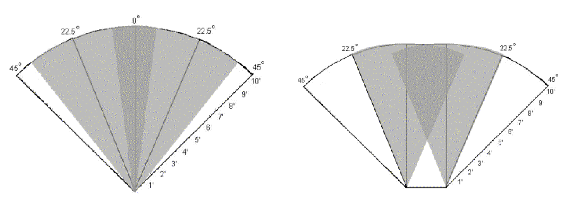
Ultrasonic sensors can detect objects placed within their range, but they cannot distinguish between different shapes and sizes. However, one can overcome this limitation can by using two sensors instead of just one sensor. One can install both sensors a distance away from each other, or they can be adjacent. By observing the overlapped shaded region, one can get a better idea of the shape and size of the target object.
References:
https://www.mouser.com/ds/2/813/HCSR04-1022824.pdf[ii] https://www.mpja.com/download/hc-sr04_ultrasonic_module_user_guidejohn.pdf
https://www.mpja.com/download/hc-sr04_ultrasonic_module_user_guidejohn.pdf
https://www.teachengineering.org/activities/view/nyu_soundwaves_activity1
https://www.arrow.com/en/research-and-events/articles/ultrasonic-sensors-how-they-work-and-how-to-use-them-with-arduino
https://en.wikipedia.org/wiki/Anemometer
https://senix.com/toughsonic-ultrasonic-sensor-sea-level-measurement/
Principles of Thermal Ecology: Temperature, Energy and Life; Clarke, Andrew. 2017
http://www.maxcessintl.com/fife
https://en.wikipedia.org/wiki/Web-guiding_systems
https://www.maxbotix.com/uav-ultrasonic-sensors.htm
https://www.mouser.com/ds/2/813/HCSR04-1022824.pdf
http://cmra.rec.ri.cmu.edu/content/electronics/boe/ultrasonic_sensor/1.html
https://www.egr.msu.edu/classes/ece480/capstone/fall09/group05/docs/ece480_dt5_application_note_nkelly.pdf
https://www.egr.msu.edu/classes/ece480/capstone/fall09/group05/docs/ece480_dt5_application_note_nkelly.pdf
Hii I am interfaced node mcu with ultrasonic sensor to know about water level in my home upstair for automatic motor on and off Throw IoT, I used pub nub console for demo purpose first I connected the node mcu and relay board, with single power source it was working properly, After I connected two different power supplies in real time operation the data was send throw pub nub relay data light was blinking but relay was not operated I don’t know what’s the wrong any body have solution ????
Hi, Sravya, and thank you for your questions. The best place to get an answer would be to visit one of our online, engineer-to-engineer support forums. There are lots of smart folks there who can help you answer your question. Visit edaboard.com or electro-tech-online.com (or both!), register, and then post your question.
Cheers,
Aimee Kalnoskas
We are looking for a sensor which can detect a fast travelling object(air gun pellet with speed between 600 to 100p fps) on target board. Accuracy/precision should be in 0.1mm in an area of 1ft × 1ft.
Could you suggest which sensor will be best.
Please do copy of reply toy email address also
Hi..is this ultrasonic sensor use the application of thermodynamic and heat transfer? Thank you