Part 1 of this article looked at the classic, highly refined, mature gyroscope-based IMU used for the Apollo moon mission; this part looks at the very different technologies which have largely replaced it.
Gyro-based IMU: obsolete, or not?
Inertial navigation relies on a stable platform with an orientation which is fixed in space and maintains that orientation despite acceleration and rotation. Key to the inertial platform is the gyroscope, which actively resists any twists and turns and is combined with a trio of accelerometers for the complete instrument.
Inertial systems based on gyroscopes are capable of astonishing accuracy. Due to many years of refinement in design, production, and analysis of shortcomings, their many subtle mechanical, thermal, and electronic imperfections and sources of error have been identified and overcome; the addition of error-correcting calibration software has further improved their performance. A gyro-based IMU can guide an aircraft or missile to a goal within a few hundred meters (much less than a mile) over a distance of several thousand kilometers (or miles) – truly impressive.
A three-axes, gimbaled gyro-based IMU was the unit that guided the Apollo command module throughout the mission. As with all three-axis gimbaled gyros, there is one major unavoidable weakness in the arrangement, called “gimbal lock.” This occurs when the three gimbals of the gyro align, so there is not external rotating force on the assembly, and so it is “stuck.” (A rough analogy would be when the pedals of a bicycle are exactly at the top/bottom of their rotation cycle: pushing straight down will not move the pedals, so you have to push them forward; in contrast, when the pedals are even a little bit offset from absolute top/bottom, a downward push will get them started.) For Apollo, unique enhancements were added to minimize (but not eliminate entirely) the possibility of gimbal lock.
Beyond the rotating-mass gyro-based IMO
Despite the refinement and associated high accuracy of the gyroscope-based IMU, the mechanical complexity, size (about same as a basketball), weight (about 100 pounds) maintenance issues, and power demands (100-200 W) were the incentive for post-Apollo IMU designers to look for alternatives to meet the needs of commercial, non-military/aerospace markets. There was special emphasis on ways to eliminate the many moving parts: the gyro rotor, electrical slip rings, sensors, torque motors, bearings, transducers, and most of all, the three-axis gimbaled assembly.
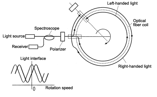
In the 1960 and 1970s, a radically different approach became feasible, first with the interferometric ring-laser gyro (RLG) and then with its cousin, the fiber-optic gyro (FOG) (Figure 1). In a broad sense, both the RLG and the FOG use the same relativistic principle to determine acceleration. In the FOG design, a laser beam is optically split and sent clockwise and counterclockwise into a long, coiled optical fiber. Any rotation motion around the coils axis translates into phase shifts between the two beams when they recombine, as a consequence of relativity principles and the Sagnac effect. Acceleration in any direction is resolved by using three orthogonal fiber loops.
The RLG/FOG’s advantages over gyro-based IMU are dramatic: it has no moving parts, and it is also installed differently. Instead of needing a multi-axis gimbal to maintain a stable orientation in space as the vehicle moves, the RLG/FOG is “strapped-down” to the vehicle it is in, which greatly simplifies the mechanical installation and initial calibration. As a consequence of this strap-down design, it does not report the vehicles acceleration or changes in orientation relative to the stable, fixed-orientation inertial platform, but instead tells the navigation system what changes it is “personally” sensing. This information is then converted to useful navigation information via extensive numeric computation.
The strapdown RLG/ FOG provides mechanical simplicity and lower cost, with smaller size and lower power need compared to a gyro-based system, but at a tradeoff in computation demands – a technical cost which is not a burden now, due to the processor advances of recent years. The first RLGs were installed on commercial jets in the mid-1980s; with a decade, they were standard on all commercial aircraft; they were soon displaced by the lower-cost, more rugged, less expensive FOG.
But now, even the FOG has serious competition from MEMS-based IMU components and complete systems. These integrated units cost anywhere from just a few dollars for a basic function such as a mid-range accelerometer or low-performance IMU (such as used in basic consumer drones and autonomous vehicles), to about a hundred dollars for a high-end version. Although even a high-performance MEMS-based IMU is not as accurate and stable as a high-end gyro-based or FOG unit, its specifications are often more than adequate for many applications, and they are getting better at a rapid rate.
As a result, the extremely small size, high reliability, low cost, and low power needs of a MEMS-based IMU now make it the choice for all mass-market applications and many commercial ones. The gyro-based IMU is now used only in extreme application such as submarine, guided missile, or deep-space systems. Due to the dramatic advantages of MEMS approaches simultaneously across multiple system parameters, carefully tuned and calibrated MEMS-based designs are being incorporated even into those applications which demand the ultimate in performance.
Reality is that the days of the spinning-rotor IMU are coming to a close. The combination of GPS for Earth-based navigation (which can be accurate to better than a meter under favorable circumstances) plus MEMS-based IMUs which include fairly precise accelerometers and vibrating-mass gyros, along with low cost, small size, low power, and ease of use via a digital interface is radically altering the GNC decision.
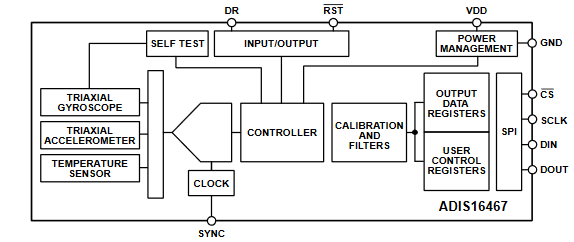
For example, the Analog Devices ADIS16467 (Figure 2), is (to quote directly from its datasheet) “a precision, MEMS IMU that includes a triaxial gyroscope and a triaxial accelerometer. Each inertial sensor in the ADIS16467 combines with signal conditioning to optimize dynamic performance. The factory calibration characterizes each sensor for sensitivity, bias, alignment, linear acceleration (gyroscope bias), and point of percussion (accelerometer location). Therefore, each sensor has dynamic compensation formulas that provide accurate sensor measurements over a broad set of conditions. The serial peripheral interface (SPI) and register structure provide a simple interface for data collection and configuration control. The ADIS16467 is in an aluminum module package that is approximately 22.4 mm × 24.3 mm × 9 mm with a 14-lead connector interface.”
IMU modules such as these are accurate enough for many applications, and some even include an integrated GPS receiver subsystem which can work in tandem with the IMU. Given this reality, the gyro- or optical-based IMU, such as used for the Apollo program and other critical missions, is clearly reaching he “obsolete” classification for all but a few highly specialized applications. But it has served well for the Apollo program and other critical applications and represents a level of refinement and sophistication that its early inventors would marvel at and also appreciate.
EE World References
Gyroscopes, Part 1: Context and mechanical designs
Gyroscopes, Part 2: Optical and MEMS implementations
GPS, Part 1: Basic principles
GPS, Part 2: Implementation
Thales announces InterSense NavChip Series 3 precision 6-Axis IMU
High-performance MEMS inertial module targets demanding AR, VR, and tracking apps
Open-source, 9-DOF inertial measurement unit carries CAN, RS232 interfaces for 12 and 24-V vehicle systems
GUI for advanced inertial measurement simplifies motion-sensing
MEMS inertial accelerometer now offered in ±10 g and ±50 g ranges
Inertial Measurement Unit (IMU) delivers high accuracy in high-vibration drone and robotics applications
IMU unit boasts 9k-byte FIFO and MIPI I3C serial interface
External References
- William Wyatt Davenport, “Gyro!: The Life and Times of Lawrence Sperry,” Charles Scribner’s Sons, 1978.
- Donald Mackenzie, “Inventing Accuracy: A Historical Sociology of Nuclear Missile Guidance,” MIT Press, 1990.
- Anthony Lawrence, “Modern Inertial Technology: Navigation, Guidance, and Control,” Springer-Verlag, 1998.
- Oliver J. Woodman, “An introduction to inertial navigation,” University of Cambridge Computer Laboratory.
- Kenneth Gade, “Introduction to Inertial Navigation,” Forsvarets Forskninginstitutt.
- Barbour, Elwell, Setterlund, “Inertial Instruments: Where to Now?,” Draper Laboratory/ AIAA Guidance, Navigation and Control Conference, August 1992.
- “The Guidance of Space Vehicles,” NASA.
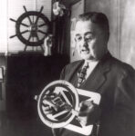
- ” Lawrence Sperry: Autopilot Inventor and Aviation Innovator“
- Neubrex Co., Ltd., “Fiber Optic Gyroscope development”
- Analog Devices, ADIS16467 Data Sheet
- The Charles Stark Draper Laboratory, Inc, P-357, David G. Hoag, “The History of Apollo On-Board Guidance, Navigation, and Control” (1976).
- Richard H. Battin, “An Introduction to the Mathematics and Methods of Astrodynamics,” American Institute of Aeronautics and Astronautics.

Leave a Reply