
Transforming the gyroscope from a child’s toy to a precise guidance system for the Apollo moon landings demanded the ultimate in analytical, engineering, and manufacturing effort: now, MEMS-based units have largely replaced these gyro-based systems.
With the 50th anniversary of the Apollo manned lunar landing on July 16, 1969, 9:32 AM GMT-4, there have been many retrospective articles and video specials on what it took to make it happen, including astronauts, engineers, scientists, production people…it’s long and always incomplete. One of the many technical advances – yet one that is often overlooked because of its “invisibility” – is the role of precision guidance and navigation via a gyroscope-based inertial measurement unit (IMU) in every aspect of the journey.
We now take tiny, low-cost, light-weight MEMS-based IMUs for granted, as they are used in consumer and mil/aero drones, munitions, autonomous and semi-autonomous vehicles, and more. But this is a relatively recent situation. This type of IMU did not exist in any form in the Apollo period, nor did GPS, although it would have been useless anyway beyond low-Earth orbit. (I did hear one TV “pundit” say that getting to the moon should have been an easy trip, with GPS to guide the craft — that pretty much typifies the expertise of some of these on-air commentators.)
Some observers of the history of science and technology note we are now in the third stage of using technology for guidance, navigation, and control (GNC). The first stage was using the Sun and compass, eventually aided by a clock for determining longitude; the second was based on inertial navigation using gyroscopes and accelerometers; and for the third stage, we have now-ubiquitous global positioning system (GPS) often tightly linked to MEMS-based IMUs.
While using Sun and compass is now a skill with greatly reduced importance due to GPS, the availability of GPS has not at all eliminated the need for inertial navigation. Whether it’s because there is no GPS access underground, underwater, or out in space, or due to concerns about unintentional or malicious interference, there will always be a need to know where you are and where you going using the completely self-contained system of the inertial measurement, It needs no external signal and functions despite electrical noise, radio interference, spoofing, and total electromagnetic shielding.
By definition, an inertial system responds only to sensed motion and acceleration with respect to an inertial frame of reference. The IMU uses basic principles of physics to determine position from the three-axis acceleration signals. By integrating these signals, the IMU determines the velocity vector; integrating them again yields position. Early IMUs performed the integration via mechanical means (difficult but it can be done) but as soon as tube-based operational amplifiers (op amps) were available, they were configured as analog integrators to do this electronically with improved accuracy and flexibility. The tube-based units were then superseded by solid-state modules, and then by ICs which were smaller, lighter, and lower power.
Sperry and Draper meet the GNC challenge
Navigating a ship over open water is difficult. But as a ship’s speed is generally relatively slow, there is time in many cases to navigate using the stars and Sun, plus sextant and compass – if conditions are right. Still, the inaccuracies of the compass, the need to make star sightings, and the time and effort needed to perform the large number of calculations and corrections needed to translate the raw readings into final position data are weaknesses of celestial navigation.
The development of aircraft put pressure on these limited navigation tools. Poor viewing conditions (fog, clouds), the high speed of aircraft and thus a need to know quickly, and the risks of not knowing where you were in the airplane meant that new approaches were desperately needed to implement as guidance, navigation, and control. Even a small angular error in the compass reading becomes a large error in position after just a few miles.
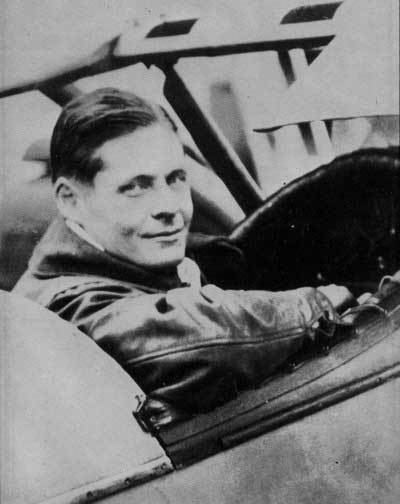
These shortcomings led Elmer Sperry to develop the gyrocompass, which uses a single-axis gyroscope (gyro) to maintain a fixed orientation towards true north, regardless of the ship’s position. The first problem was to develop a system which could at least maintain a constant heading while flying. Lawrence Sperry, Elmer Sperry’s son, was one of the first pilots in the early days of aviation and an accomplished inventor; he died in a crash in the English Channel in 1923 at age of 31. Lawrence (Figure 1) greatly enhanced his father’s gyrocompass design to function as an autopilot, modifying it to maintain the three flight axes (pitch, roll, and yaw) unaided by hands-on pilot action. This was the first step towards “automating” the piloting of the plan and relieved the pilot of the need to provide constant attention on long flights.
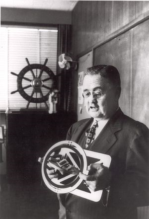
The gyrocompass and autopilot showed what gyroscopes could do and Charles Stark Draper (Figure 2), made it happen. Born in 1901, he attended the University of Missouri, moving on to Stanford University in 1919, where he completed a BA in psychology in 1922. Draper then went to the Massachusetts Institute of Technology (MIT), where he earned his SB in electrochemical engineering in 1926, an SM in 1928, and an ScD in physics in 1938.
At MIT, he conducted research related to navigation and control systems, working first under sponsorship by the Sperry Gyroscope Co. Draper became an assistant professor at MIT in 1935 in the Department of Aeronautics and Astronautics, retiring as 1966 as Institute Professor. He founded the MIT Instrumentation Laboratory in the 1930s, which was spun off in 1973 as the Charles Stark Draper Laboratory (aka Draper Labs), to be an independent, non-profit organization.
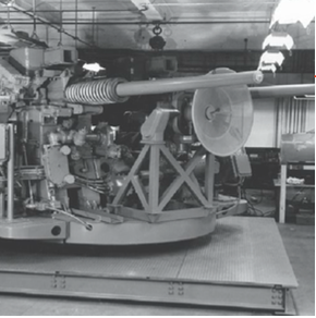
Draper had already done major and impressive work with gyros, using them in his innovations related to the MK 14 Gunsight (1942) for ship-based antiaircraft guns (Figure 3). This gun-laying system successfully accommodated the roll and pitch of the ship while also tracking and “leading” the gun’s aim against a fast-moving aircraft. Sperry Corp. built 100,000 of these based on Draper’s design in WWII.
Over the course of many years, Draper pushed the gyro-based IMU towards perfection by analyzing every first-, second-, and third-order source of error, then working to minimize it if not eliminate it. For example, Draper developed the “floated” gyro enhancement in the 1960s. First, the basic mechanical elements were as near-perfect as possible, via the use of pressurized-gas bearings rather than ball bearings. Still, there would always be unavoidable errors and offsets due to the mass of the gyro rotor being pulled down by gravity. This was a tiny but measurable second-order error source, and the solution was immersed in the entire rotor assembly in a high-density fluorocarbon fluid so as to make it have neutral buoyancy and appear weightless – roughly analogous to diving far enough below the water surface that you feel weightless (about 14 feet).
The resultant neutral buoyancy greatly reduced the mass-gravity error, but even that was not enough for Draper. Since the density of any such fluid changes with temperature, the neutral buoyancy point of this “floated gyro” would not be constant. His solution: heat the fluid to maintain it at a constant temperature (around 150⁰ to 180⁰F) to eliminate the thermal variations, thus avoiding even this tiny third-order error source.
Several examples show the extent to which Draper engineered the concept of gyro-based inertial guidance into high-performance, highly accurate systems.
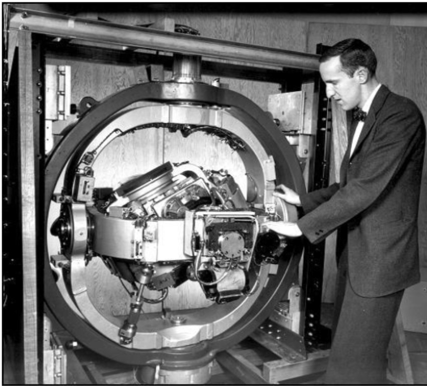
- Draper designed and built the Space Inertial Reference Equipment (SPIRE) system, then organized and took part in a cross-country airplane trip in 1953 which relied on it alone for navigation and guidance from after takeoff to immediately before landing, without any other assistance (Figure 4). The intent was to prove the viability of inertial-based navigation to skeptics, which it did.
- The subsurface transit of the North Pole in 1958 by the USS Nautilus (the first nuclear submarine) was navigated by a Draper-designed, Sperry-built inertial system. Neither magnetic compass or gyrocompass can provide reliable information close to the Pole, and star sighting is obviously impossible from under the ice cap, so the trip would have been impossible without this self-contained IMU.
- As soon as the Apollo moon-mission goals were announced, Draper committed to providing the guidance and navigation systems. He knew that along with the countless, highly visible rocketry issues of the mission, the less obvious but very vital navigation system had to be precise and accurate. Navigation is space is hard: everything is in constant motion on different curved paths, and you can’t just point where you want to go and “step on the gas.” Plus, fuel and other consumables (food, water, electrical power, and rocket fuel) are obviously limited, and there could be no “oops, we missed it, let’s just try again” retries in a lunar journey, due to limits on these resources.
Over his career, Draper received dozens of medals and awards, including the National Medal of Science in 1964. The National Academy of Engineering established the Charles Stark Draper Prize in 1988 in his honor. The prize is awarded annually and consists of $500,000 (cash) and a gold medallion.
Part 2 of this article will look at the replacement of the gyroscope-based IMU by radically different technologies.
EE World References
Gyroscopes, Part 1: Context and mechanical designs
Gyroscopes, Part 2: Optical and MEMS implementations
GPS, Part 1: Basic principles
GPS, Part 2: Implementation
Thales announces InterSense NavChip Series 3 precision 6-Axis IMU
High-performance MEMS inertial module targets demanding AR, VR, and tracking apps
Open-source, 9-DOF inertial measurement unit carries CAN, RS232 interfaces for 12 and 24-V vehicle systems
GUI for advanced inertial measurement simplifies motion-sensing
MEMS inertial accelerometer now offered in ±10 g and ±50 g ranges
Inertial Measurement Unit (IMU) delivers high accuracy in high-vibration drone and robotics applications
IMU unit boasts 9k-byte FIFO and MIPI I3C serial interface
External References
- William Wyatt Davenport, “Gyro!: The Life and Times of Lawrence Sperry,” Charles Scribner’s Sons, 1978.
- Donald Mackenzie, “Inventing Accuracy: A Historical Sociology of Nuclear Missile Guidance,” MIT Press, 1990.
- Anthony Lawrence, “Modern Inertial Technology: Navigation, Guidance, and Control,” Springer-Verlag, 1998.
- Oliver J. Woodman, “An introduction to inertial navigation,” University of Cambridge Computer Laboratory.
- Kenneth Gade, “Introduction to Inertial Navigation,” Forsvarets Forskninginstitutt.
- Barbour, Elwell, Setterlund, “Inertial Instruments: Where to Now?,” Draper Laboratory/ AIAA Guidance, Navigation and Control Conference, August 1992.
- “The Guidance of Space Vehicles,” NASA.
- ” Lawrence Sperry: Autopilot Inventor and Aviation Innovator“
- Neubrex Co., Ltd., “Fiber Optic Gyroscope development”
- Analog Devices, ADIS16467 Data Sheet
- The Charles Stark Draper Laboratory, Inc, P-357, David G. Hoag, “The History of Apollo On-Board Guidance, Navigation, and Control” (1976).
- Richard H. Battin, “An Introduction to the Mathematics and Methods of Astrodynamics,” American Institute of Aeronautics and Astronautics.
- David Mindell, “Digital Apollo: Human and Machine in Spaceflight,” MIT Press.
- Charles Murray & Catherine Bly Cox, “Apollo: the Race to the Moon,” South Mountain Books.

Little known is that the Apollo Lunar Excursion Module (LEM) had a back up guidance system known as the Abort Guidance System (AGS) that was a strapdown IMU (where there are no gimbals that are essentially replaced by software). The AGS IMU was built by United Technologies’ Hamilton Standard. All current IMUs use this strapdown approach. The AGS was used to guide Apollo 13 back to Earth because it used much less power than the primary guidance from Draper.
.
I was lucky enough to join Hamilton Standard and eventually become responsible for the AGS IMU electronics.