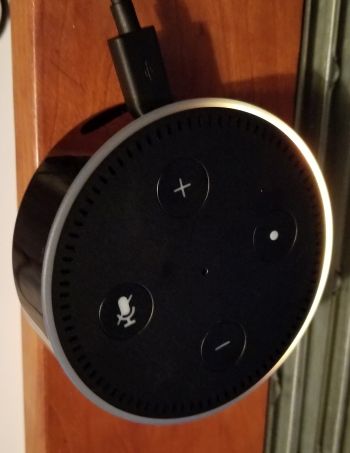
The Amazon Echo Dot is essentially the top portion of the Amazon Echo, but without the speaker underneath it. Eliminating the big speaker drops the price of the from $180 for the Echo to $50 for the Echo Dot.
 The Echo Dot does have its own speaker, but the speaker is comparable to what you might find in a laptop computer. It is intended for broadcasting the voice of Alexa, the voice of the Echo’s digital assistant. If you want the same kind of audio quality as in the original Echo, you can hook the Dot to a set of external speakers. This can happen either through Bluetooth pairing or by using the 3.5-mm stereo jack on the Dot to feed its audio to a conventional stereo system, if you happen to have one.
All the features and commands that work with the Amazon Echo work with the Echo Dot, and the setup process is via a smartphone app that is identical to the original Echo. As with the original, the Dot’s indicator ring flashes orange when you plug it in for the first time. And you still need to sign the Dot to your Wi-Fi like you would any other WiFi device.
The Dot we tore down is a second-generation device. Judging by the teardowns of first-generation Dots we’ve seen online, there are a lot of differences in the electronics that happened when Amazon updated the design though the mechanical assembly is largely the same.
The first step in disassembling the Dot is to pull off a rubber pad from the base that hides four screw holes. The screws aren’t super small and they have an ordinary Torx head on them so they unscrew relatively easily. Removing the plastic case brings a view of the main circuit board in the top half of the device and of the speaker enclosure in the other half.
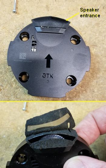
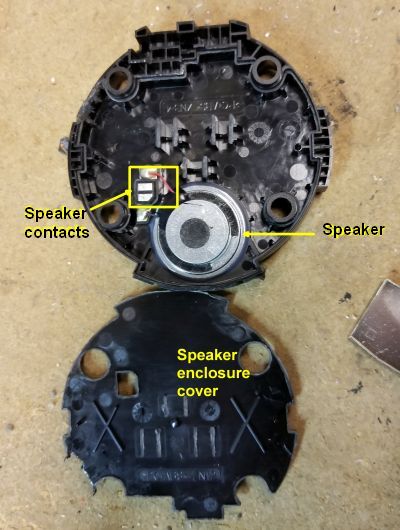
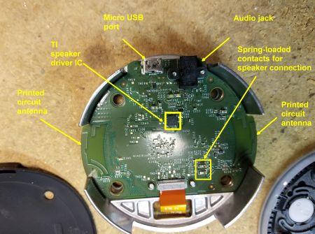
The speaker enclosure pops out of the bottom half of the Dot. The enclosure seems to be a sort of baffle focusing the sound waves out of a small opening. Removing a plastic top from the baffle reveals the speaker itself. It makes an electrical connection to the main circuit board through two metalized pads that touch small spring-loaded metal prongs on the main PCB when the device is assembled. One other interesting bit about the bottom half of the Dot case holding the speaker is that it contains what seems to be an RF-ID circuit pasted to the inside bottom surface.
That brings us to the main circuit board. Visible on the board is the Texas Instruments chip called the TLV320DAC3203 which is used to drive the speaker and produce the audio that can be fed to an external stereo. Another point of interest on this side of the board is the printed circuit antennas that are used for WiFi and probably for Bluetooth as well.
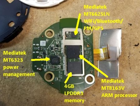
Also evident is a ribbon cable that connects the board to a second PCB that holds the user pushbuttons, microphones, and LEDs. There aren’t any fasteners holding the circuit board so extracting the cable connector allows us to remove the PCB and look at the other side. On this side, we find two big metal shields over top the RF chips. Removing the shields reveals four main chips, a quad-core ARM processor, a power management chip, and a chip that handles WiFi, Bluetooth, FM, and GPS. All three of these chips are from Mediatek in Taiwan. A fourth chip is a four-gigabit low-power double data rate synchronous DRAM, apparently made by Micron, designed for smart phones and tablets.
A point to note about these Mediatek chips is that they often can be found in budget-priced smartphones. So from the standpoint of its RF electronics, the Echo Dot looks a lot like a $50 smartphone you might buy on Amazon. Another point of interest is that other teardowns have found that this same chipset can be found in a tablet Amazon makes called the Fire HD 8.
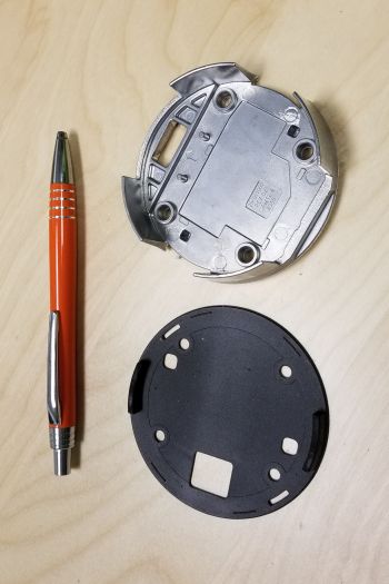
Behind the main circuit board is a big metal heatsink. This heatsink is a bit of a mystery to us. It weighs in at about 1.65 oz. That’s about the size of heat sinks we’ve found inside some LED light bulbs designed to put out as much light as 60-W incandescent bulbs. The heatsinks in those LED bulbs can get pretty warm because the bulb might hold a dozen or more high-output LEDs that are switched on for long periods of time. But there doesn’t seem to be any high-current parts in the Dot. The LEDs it contains are much smaller than what you normally find in LED bulbs, and they only illuminate periodically. So we are not sure why the Dot needs a heat sink that is this beefy.
Removing the main circuit board and the heat sink reveals a thin rubberlike membrane sitting on the top surface of the heat sink. This membrane is another little mystery. It doesn’t provide any electrical isolation. The fact that it is flexible might indicate it serves as some sort of acoustic isolation. But it is on the other side of the heat sink from the speaker, a fact that makes that theory less likely. So we are befuddled about why it is really there.
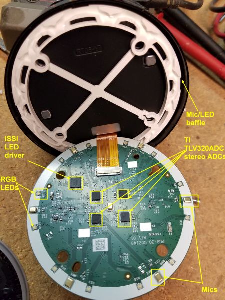
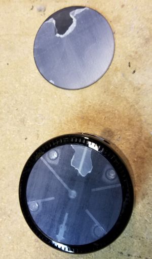
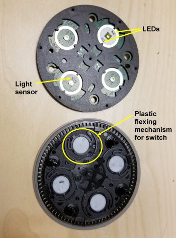
Removing the rubber membrane reveals a white plastic frame. The frame provides baffles for both the microphones and LEDs sitting around the edge of the Dot.
That brings us to the PCB that holds the control switches, LEDs, and microphones. Four tactile dome switches sit on the top of the PCB. Two of them move the volume up and down, another mutes the microphone, and the fourth is an action button. That’s a change from the first-generation Dot, which only had two buttons, one for muting the microphone, the other an action button.
The mute microphone button has two red LEDs near it to indicate that the microphone is switched off. Another noteworthy feature is a small light sensor that sites near the action button. The light sensor detects the level of room lighting and adjusts the brightness of the LEDs accordingly.
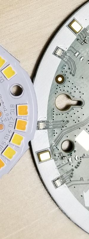
On the reverse side of the second PCB sit seven microphones and 12 RGB LEDs. Both the LEDs and six of the microphones sit around the outer edge of the PCB. Also notable is that the PCB has a white mask around its edge to help reflect the LED light and enhance the light that rings the top edge of the Dot.
Each microphone connects to a Texas Instruments analog-to-digital converter having a part number of TLV320ADC3101. Each of these ADCs accepts two inputs which explains why there are four ADCs handling eight microphones. Also on the board is an LED driver for the 12 RGB LEDs. The driver is from Integrated Silicon Solution and it is designed to handle 36 channels, each with an independent PWM control. That’s exactly what you need to handle 12 RGB LEDs because each color on each LED needs its own channel. The ISSI chip also can modulate the brightness of each LED channel to fade the LED light to create what’s called a breathing effect which the Dot puts to good use.

Nice description. I understand the WiFi and Bluetooth, but why the FM, and GPS? I have a couple of Dots, and I have seen nothing about these channels! What’s up here?
If I had to guess, FM and GPS just come along for the ride because they happen to be there in the chip — even if they’re not used. Bluetooth is quite popular with wearable devices for the fitness market, and probably somebody said, “We can track the mileage on this guy’s run and give him a radio function to feed his earbuds if we wrap it all into one chip.” This is actually pretty common, and my company is currently designing with a few wireless datacomm controllers with extra features we’ll never use just because they have features we do and the price is right.
That is probably not a heatsink but rather just a bit of metal to add weight to the device in order to make it not feel like a cheap, lightweight piece of junk. As for the rubber bit, my guess is that it’s purpose is to stop the metal bit from rattling.
Do you know what is the plastic/acrylic diffuser film they might be using for the light ring?
It’d be great if you could provide info. on the LEDs they are using?
Terrific breakdown! I appreciate you identifying the DAC. Would you happen to know what that kind of speaker is called? Or where/how I might find a similar one?
WOW That’s a great teardown!
Does anybody know the exact name or specification of the LED driver from Integrated Silicon Solution
Led driver part No, IS31FL3236, this is 36 channel LED driver.
Thanks,
my unit is not turning on, can it be the power management chip and if so, where can I get one?
Why does it need 4 gigabytes of ram?
Anyone know what the part number of the light sensor is?, I am looking for the datasheet for this component.
I am trying to modify it so that the LEDs stay full brightness and do not dim.
Ant.