Here is what the architecture of modern-day dual-speed Ethernet/Wi-Fi router looks like these days.
TP-Link’s Archer C7 dual-speed wireless router delivers 1,300 Mbps over the 5 GHz band and 450 Mbps over the 2.4 GHz band. That should be enough bandwidth for HD streaming, online gaming and other bandwidth-intensive tasks. The idea behind using two bands is to handle 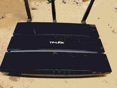 simple tasks like web browsing on 2.4 GHz and bandwidth-intensive operations on 5 GHz. Both bands are operational simultaneously. This wireless router also has a 1 Gb WAN port and four 1 Gb LAN ports.
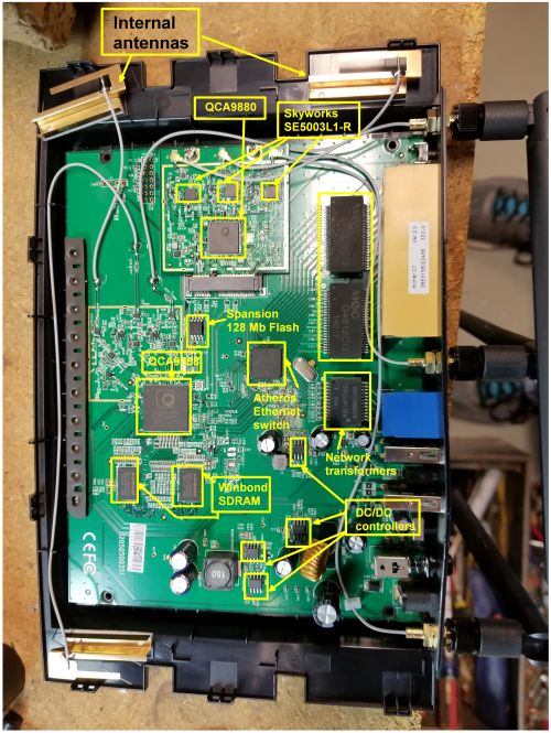
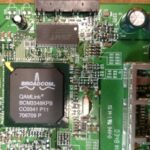
Most wireless routers made today are built around three main chips and the TP-Link router is no exception. It uses a chipset from Qualcomm. The main device is a QCA9558 dual-band three-stream 802.11n system on a chip. It contains both the radio circuits for 2.4 GHz band and the baseband circuitry for managing Ethernet connections. Also on the main board is a Qualcomm AR8327 seven-port gigabit ethernet switch.
 There is another Qualcomm 802.11 radio chip called the QCA9880 that sits on a separate board along with three RF power amp chips from Skyworks. This is the chip that handles the 5 GHz wifi.
Thus the main 802.11 chip on the motherboard handles 802.11n transmissions taking place at 2.4 GHz. The main difference between 802.11n and earlier versions of 802.11 is that the ‘n’ spec added provisions for multiple-in-multiple-out antennas or MIMO antennas. This spec has been around since about 2007.
The 5 GHz band is what’s called 802.11ac. That version of the spec came along around 2013. Also, 802.11ac signals have different qualities than those following 802.11n. Those differences include wider channels (80 or 160 MHz versus 40 MHz), more spatial streams (up to eight versus four), use of higher-order modulation (up to 256-QAM vs. 64-QAM), and the addition of Multi-user MIMO, though the TP-Link router doesn’t actually support the multi-user style of MIMO.
Another interesting point is that this three-chip architecture is the same one you’ll see used on other wireless routers, even those that use a chipset from some other supplier. That seems to be because the 802.11 chip makers put out reference designs for use with their 802.11 chips that are the basis for most commercial wireless router boxes. The use of these reference designs leads to a lot of commonality among different brands of wireless router hardware.
For one example, on the TP-Link motherboard you’ll find base-T dual port transformers from Mentech and a network transformer from Group-Tek, as well as two 16-bit DDR2 synchronous DRAM chips from Winbond. We’ve seen these same devices on motherboards from other wireless router makers. The similarities are such that these devices even occupy spots on the circuit board that don’t vary much from one wireless manufacturer to another.
There’s another similarity among different 802.11 chip makers: Most don’t release much information about their chips. For example, you can’t find data sheets for the two Qualcomm 802.11 chips online. On another wireless router we’ve examined, the router manufacturer put adhesive foam pads over the three main chips. Pulling off the adhesive also removed the markings on those chips. Apparently, the adhesive was there to make it almost impossible to read the chip markings. It didn’t seem to serve any other function other than to complicate the teardown process.
There are a couple other observations we can make about T-Link’s board. We note that the 802.11 chip for the 5 GHz band sits on its own mezzanine-style board, along with three RF amps from Skyworks. There doesn’t seem to be any technical reason to put this chip on its own little board. The backside of the board is basically empty, so it wasn’t done for purposes of board density. Our guess is that this T-Link router design originally handled just the 2.4 GHz 802.11 band and the 5 GHz facilities were added. We’d also suspect that later versions of this wireless router integrate the 5 GHz chip onto the main circuit board.
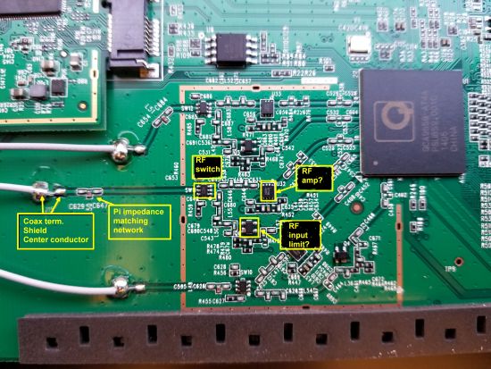
The final aspect of the router we’ll comment on is the antenna and RF signal handling system we found. There are fine wires, apparently 16 awg, running between the antennas and the RF front end on the router. At first, we thought these might be bare wires, which would be odd for handling signals in the single-digit gigahertz range. But a close inspection of the wires reveals they are actually very fine coax cable which makes more sense.
The signal-handling path from the end of the cable to the 802.11 chips is also interesting. The cables for the 2.4 GHz signals are soldered directly to the circuit board. A close-up look at the board shows the shield soldering and fine soldering of the center conductor a few millimeters beyond.
We can also make out a few other features of the signal path from the antenna connection to the 802.11 chip. The three components located there form a pi network for matching the impedance of the antenna to that of the RF input. Next comes a solid-state switch IC that switches the antenna connection between the RF receiver input and the transmitter output, so the 802.11 radio can transmit and receive on the same antenna.
In one path after the switch, we find what we speculate may be a diode network there to make sure large input signals don’t overload the front end of the RF receiver. On the other signal path, we find a chip that may be an RF amp, there to boost the RF output sent to the antenna. These circuits are identical on each of the three paths for the 2.5 GHz antennas.
All in all, the reviews we’ve seen of this router give it good marks as a higher-end device without the price tag. It delivers its features using chips from well-known suppliers.

Unfortunately, mine stopped working after one year.. Actually bricked.
Are all the external antennas connected to the 5ghz chip?
I can’t tell if the antenna in the top-right of the photo is going to the 2.4 or the 5 ghz chip. I have an external directional antenna that I want to use on a 2.4 ghz band.
Yeah, it seems to be that 5G uses the external antennas and 2.4G uses internal.. and I too was planning to use it as a access point with outdoor roof antennas, oh well. 🙁
I never thought the Archer C7 was that great, the big issue for me is finding out there are no heat sinks on the chips not even the primary ones. Just incredible you create a higher bandwidth router with no ability to cool chips properly. Its no wonder experiences of weak signal and drop outs occur. The firmware was also a mess for awhile as it took too long to fix some of the major issues. Not sure if the versions 3 and up ever addressed some of these problems? Won’t buy another TP Link router, at the time this was a mid level router that wasn’t worth the price I paid for it. Now days it can had for around $50 that’s all its worth at best. So many of these router makers are concerned more with design and looking like spaceships then reliability. My advice is buy a business class router next time, its more flexible and concerned more about function and reliability.
I have this incredibly annoying issue with my C7 – it constantly drops the PPPoE connection on the WAN port. It’ll work for maybe a day, a week or a month but then it’ll drop the connection and say that the WAN port is unplugged. Once the connection is dropped, the only thing that will get it back again is to physically unplug the ethernet cable from the WAN port and plug it back in. Reboots have no effect.
There must be something extremely wrong with the switch that’s connected to the WAN port if it’s doing that. I’ve often noticed the auto-negotiation speed of the WAN link varying. It’ll start out at 1Gbps, then return at just 100Mbps, I’ve even seen it drop to 10Mbps. It turns out it’s not an uncommon issue on TP-Link routers either.
Things I’ve tried (to no avail)
* Restricted the auto-negotation speed of the WAN port to 100Mbps by making my own ethernet cable and crimping only two of the twisted pairs.
* I thought it might be buggy firmware, so I tried the DD-WRT firmware. It seemed to solve the problem and worked better, but the issue re-occured.
* Used some of the LAN ports as the WAN port by swapping around the VLAN they’re on using DD-WRT. Works for a while, but the issue re-occurs again.
I’m suprised with reviews being so positive that more people haven’t noticed this issue. This router is now effectively useless to me as a result.
My advice – Avoid, Avoid, Avoid.
For people with the C7.. Mine is a V2 common issues.. I run mine NAT enabled but hardware NAT support disabled or whatever disabled.. I get better performance this way all around it seems.. Not I live in apartment.. I took channel 1 around me for 2.4ghz and distance.. You may get disconnects over 5G.. I upgraded a sheisty antenna no issues there.. Channel Banding and width is important and apparently in high density areas the 5g side just can’t cope.. I set auto / auto and havent had a problem since.. your420guy.ca Your welcome!!
I don’t see a mention of what hardware version this unit that you toredown was? I have a Archer C7 v2 and I am wondering whether it has the same config as the one in this article.