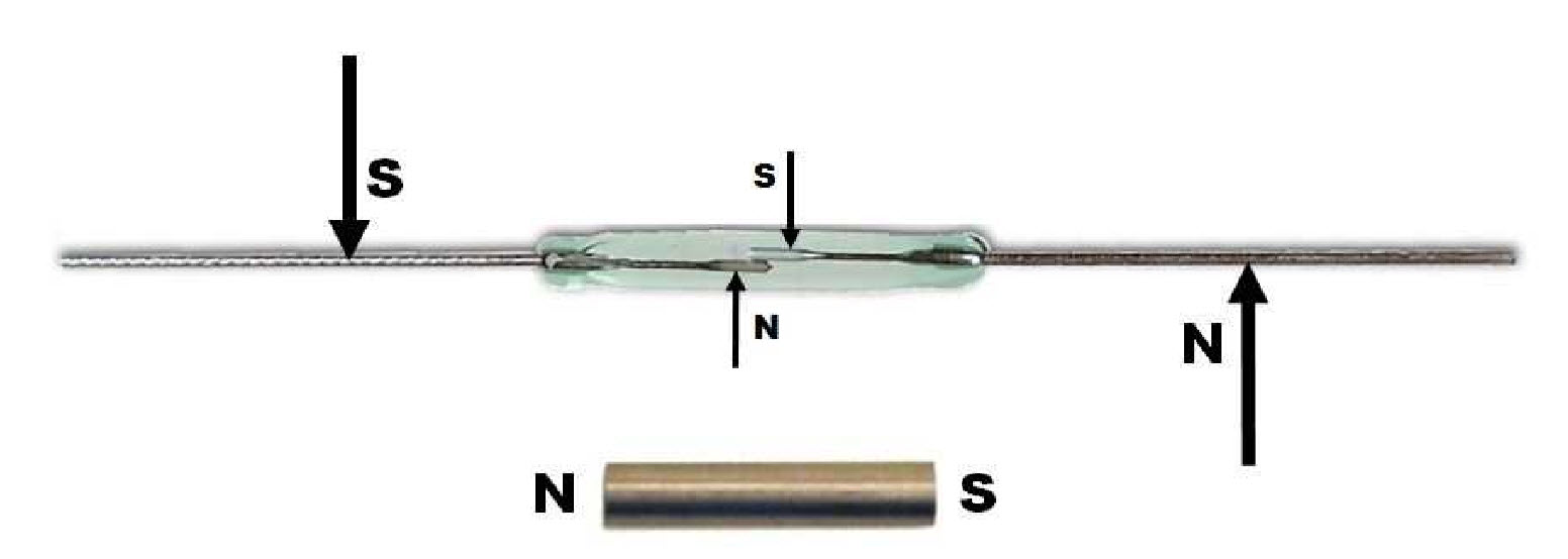
Reed switches are simple, passive, electromechanical components that were invented circa the 1940s. Reed switches aren’t mentioned much in electronic literature or forums that much, but they have some amazing capabilities. Reed switches are sometimes called magnetic switches. Reed switches open or close when exposed to a magnetic field. The reed switch consists of a couple of contacts made of magnetically sensitive materials (reeds) that are hermetically encapsulated in a glass envelope. The reed switch opens or closes when a magnet is near. When the magnet is removed, the reed switch returns to its normal position. The strength of the magnet required to actuate the reed switch is measured in units of gauss, found in the datasheet for the component.

Why not use a Hall effect sensor?
Hall effect sensors also operate when exposed to a magnetic field. However, there are some interesting differences. Hall effect sensors are solid-state (semiconductor) devices that can trigger an external relay with a low voltage output signal. Hall effect sensors require constant power to operate. Even when the Hall Effect sensor is not detecting a magnetic field, it needs to be powered on so it can be ready to sense a magnetic presence. A reed switch is both the sensor and the contacts in one element and needs no power to do its job. Reed switches conduct electricity through the reeds that act as contacts and also move upon detecting magnetic field, thus requiring no external parts; the reed sensor is the switch, too. Reed switches can be used over a wide temperature range, in all types of harsh and dirty environments, and come in a wide variety of shapes and packages (the glass surface mount type is shown in Figure 1.) Hall Effect Sensors are polarity sensitive, whereas Reed switches are not. Both reed and Hall sensors offer contactless operation with a magnetic field as a trigger. The ON state resistance of a Hall Effect sensor is at least 10 times that of Reed switches. Reed switches can withstand a three foot drop test, similar to that of Hall Effect sensors.
Some reed switches can operate at a greater distance from the magnetic source than a hall effect sensor, given the same magnetic flux as a trigger. If positioning is a big deal, you should know that Hall Effect devices need to be placed orthogonal to the magnetization axis of the magnet, whereas for a reed switch, you need to place the magnet’s field axis parallel to the reed switch. The simple reed switch is hardy and requires no power, but the Hall Effect sensor is more sophisticated in that it can determine the direction, as well as the rate at which it passes the magnetic field. Many Hall Effect sensors are packaged together with a relay or transducer and circuitry to provide an all-in-one contactless solution. However, sometimes the reed switch might be all that is necessary. Reed switches are used in medical devices such as defibrillators, in automotive safety systems, and in automatic test equipment for integrated circuits.
Table 1: A comparison of Reed Switches vs. Hall Effect Sensors
| Parameter | Reed Switch | Hall Effect Sensor |
| Form Factor | Moving parts/electromechanical | Solid State |
| Physical size | < 4 mm long (glass encapsulate) | IC package can be < 2 mm plus leads |
| Touch-free sensing | Yes | Yes |
| Voltage Switching Range | 0 – 1000 V | Signal output in milli-volts |
| Switching time | < 100 µs to operate | < 10 µs to operate |
| Load switching | Switches loads directly | Sensor needs external circuitry to switch a load |
| Switch operations in a lifetime | Billions | Billions |
| Voltage output offset | Not applicable | Required to adjust for temperature or thermal stress |
| ESD Protection Required | No | Yes |
| Vibration limits | 10 g | > 50 g |
| Power required to sense & operate | No | Yes |
| Operating Temperature | 0° – 70°C, outside of which temperatures will affect performance. | -55° – 150°C |
| Polarity sensitive | No | Yes |
| External circuitry that may be required | None | If not integrated into the Hall Effect sensor chip, it may require the following: amplifier, chopper, voltage regulator, ESD protection, external filter and switch |
| Senses both rate and direction of a magnetic field | No | Yes. Less likely to lose count of revolutions. |
| Latching capability | External circuit required | Additional circuit required that may be included in the integrated chip package |
References
Hamlin application note AN104
https://www.kjmagnetics.com/pdfs/AN102A.pdf
Leave a Reply