MCU start up is a highly structured process designed to ensure proper operation. Numerous elements are involved including initial power/voltage sequencing and regulation, oscillator startup, the use of a vector table, boot loaders (including possible secure boot), and application initialization. This FAQ walks step-by-step through the various elements involved during the start-up of an MCU.
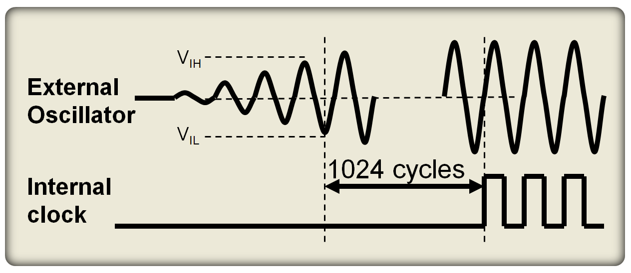
When power is first applied, the MCU waits for two things; the voltage to stabilize an oscillator to generate a stable signal. Crystal oscillators take a finite amount of time to stabilize. MCUs can address that delay with an oscillator start-up timer (OST). When power is applied, the initial oscillations have unstable amplitudes and periods, but after a brief time (or a given number of oscillator clock cycles), operation stabilizes (Figure 1). If the MCU begins loading software before the oscillator stabilizes, its operation can be negatively impacted. The OST can be invoked every time the oscillator is restarted such as on a power-on reset, brown-out reset, or waking up from sleep mode, not just at the initial power up. If there are multiple oscillators, each can have an independent OST with different timing criteria.
After the power source voltage and oscillator output have stabilized, the MCU uses the reset vector (in the vector table) for the location of where the start-up instructions (the boodloader) are in Flash memory. The reset vector, sometimes called the reset handler function, also performs hardware initialization including:
- Disables all interrupts
- Initializes data segment
- Initialize the .Bss segment
- Initialize stack segment
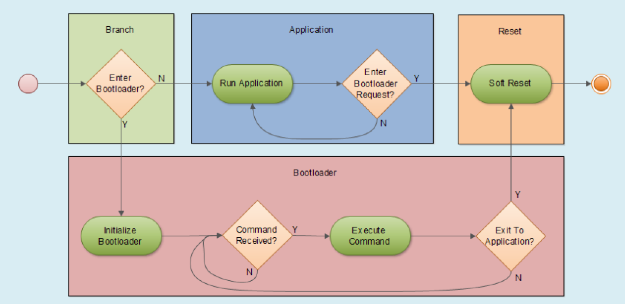
When an MCU is powered off, the program code and data is stored in non-volatile memory. When the MCU starts up, or is reset, the bootloader is used to initialize the system and load program code and other essential data. While there are many specific implementations of bootloaders, they generally share four major elements (Figure 2):
- Branching code (green) that decides whether the bootloader or the application is loaded.
- Application code (blue) is executed if the branching code determines that the bootloader is not needed and that the application code is safe to execute.
- Bootloader code (red) is the key during startup and begins by initializing the peripherals that are required in order for the bootloader to perform all of its functions. These peripherals are typically the system clock, interrupt service routines and tables, a communication peripheral and perhaps a state-machine or basic task scheduler.
- Code shared by the bootloader and the application to reset the system (orange)
The bootloader code is responsible for preparing the runtime environment for the application. Once the bootloader has completed its primary tasks, the installation verification test (IVT) routine is run. The IVT confirms that the installation of the application server profile was correct. The profile contains all the files needed to define the runtime environment Next, the application code and other data are loaded onto RAM and the MCU begins running the application program.
Secure boot
A basic bootloader is suitable when security is not a major concern. The explosion in the use of connected devices in business-critical systems has increased the number of threat vectors making it important to secure device operation. When there are concerns related to security that need to be addressed, a secure bootloader process is employed. During a secure bootloader process, the operating system images, code and other elements of the runtime environment are authenticated before they can be used by the boot process. The hardware uses trusted security credentials to authenticate the bootloader code to ensure they have not been tampered with or altered by any outside source.
A secure bootloader prevents an adversary from installing a different bootloader, or compromising the operating system or executable code. Without the use of a secure bootloader, any malicious code inserted into the device could enable a malicious actor to take control of the system, accessing sensitive data, making the device part of a botnet, or even physically damaging system operation. The use of a secure bootloader includes security checks during booting or rebooting that identify unauthorized code, prevents it from running, alerts the user and/or takes other remedial actions.
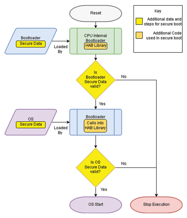
A secure bootloader goes through a series of process steps designed to guarantee the integrity and authenticity of the boot process and the application software (Figure 3). Verification that the bootloader is authentic and unmodified is the first step. That verification is performed using public/private keys. During the development of the secure bootloader, the code is digitally signed with the manufacturer’s private key. Its authenticity is checked when the bootloader code is run by checking it against an embedded public key of the device. The same process is used very time the device boots and every time an update is installed. After the bootloader has been confirmed to be authentic, the operating system, runtime environment and applications are also verified using a public/private key process. The system starts running only after all of the elements have been confirmed to be authentic.
Summary
When an MCU starts running, the first thing that happens is that the start-up process pauses until the basic power rail(s) and the oscillator have stabilized to ensure proper operation. Once the system is electrically stabilized the bootloader is used to initialize the runtime environment of the device. Next, the IVT confirms that the installation of the application server profile was correct, enabling the startup of the application software. In a growing number of connected systems, the basic bootloader is replaced by a secure bootloader using public/private key technology to ensure that none of the system elements, including the bootloader itself, have been tampered with or altered by any outside source.
References
Bootloader Design for Microcontrollers in Embedded Systems, Beningo Engineering
Interrupt vector table, Wikipedia
Oscillator start-up time, Microchip
What is Secure Boot? It’s Where IoT Security Starts, Keyfactor
Why Would You Use a Secure Element for Secure Boot?, Microchip