Positive feedback is primarily used to rapidly amplify a desired change or signal, often in situations where a large response is needed, like triggering a process to reach a specific threshold quickly. It must be carefully managed due to its potential for instability and runaway effects. It’s used in digital electronics to force voltages away from intermediate voltages into ‘0’ and ‘1’ states.
A simplified view of an industrial control system is shown in Figure 1. The input signal is processed using the amplifier gain (A) of the control circuitry and algorithms to produce the output. The feedback transfer function (B) returns a portion of the output signal to the input side, which is combined with the input signal to adjust the output.
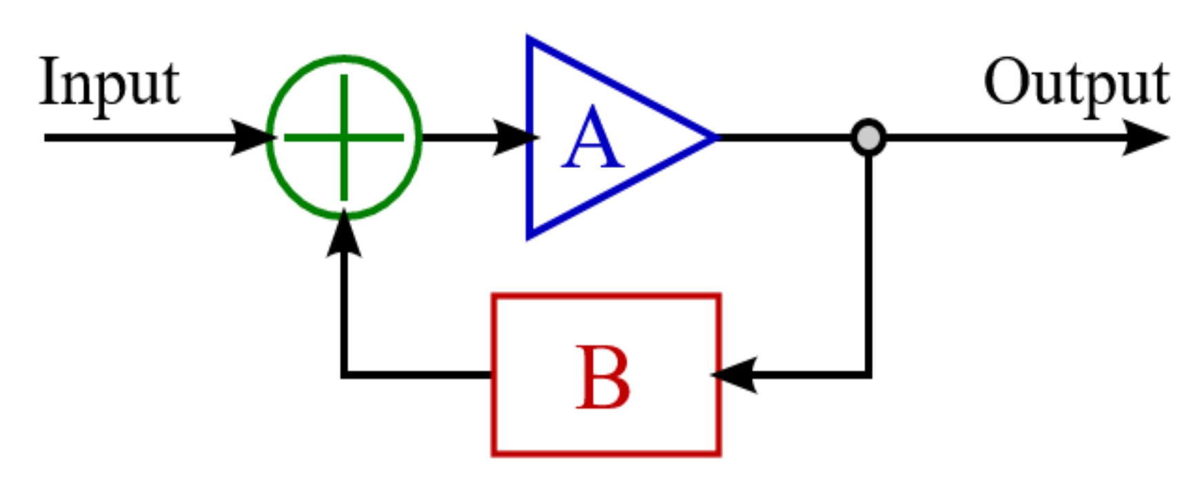
In this simple linear system, loop gain (GC) can be defined relative to (linear) A and B: Gc = A / (1 – AB). The key is AB. If AB is <1, the gain is finite but can become very large (and potentially dangerous to stability) as AB approaches 1. The danger increases if AB is >1, the system becomes unstable, and the output can diverge from the desired value.
Despite the downsides and dangers, positive feedback can be beneficial in industrial processes:
- Electric signals can often benefit from amplification using positive feedback, potentially improving performance, but this can also result in regenerative situations, increased noise and transients, and instability.
- Mechanical mechanisms using positive feedback can exhibit tipping-point behaviors, such as switches, which support rapid control functions or result in unexpected and unrecoverable outcomes, like unchecked acceleration.
- Chemical processes with positive feedback can benefit from increased reaction rates, but they can also experience runaway reactions, even leading to explosions.
Averting danger
Designers have several options for averting the dangers associated with implementing positive feedback.
One simple approach is to filter or dampen signals to reduce the amplitude of feedback. That can reduce the tendency toward excessive output swings, but it can also reduce the system’s response time.
Adding negative feedback to bring the system to a stable point, while positive feedback is used to accelerate and amplify changes until the stable point is reached.
Active control can be added with terms for maximum output settings or saturation limits to moderate the system’s ability to amplify the initial feedback signal.
Positive feedback for digital circuits
Schmitt triggers are a common example of positive feedback in electronics. A Schmitt trigger is a type of comparator circuit that creates two distinct thresholds for the input signal. It’s a latching circuit that uses positive feedback to reach either the upper or lower limit quickly.
A Schmitt trigger can be used to convert an analog signal into a corresponding digital signal (Figure 2). Changes in the output are triggered when the input value exceeds one of the threshold values (green dashed lines in Figure 2 U). When the input value falls between the threshold values, the output is latched and remains unchanged.
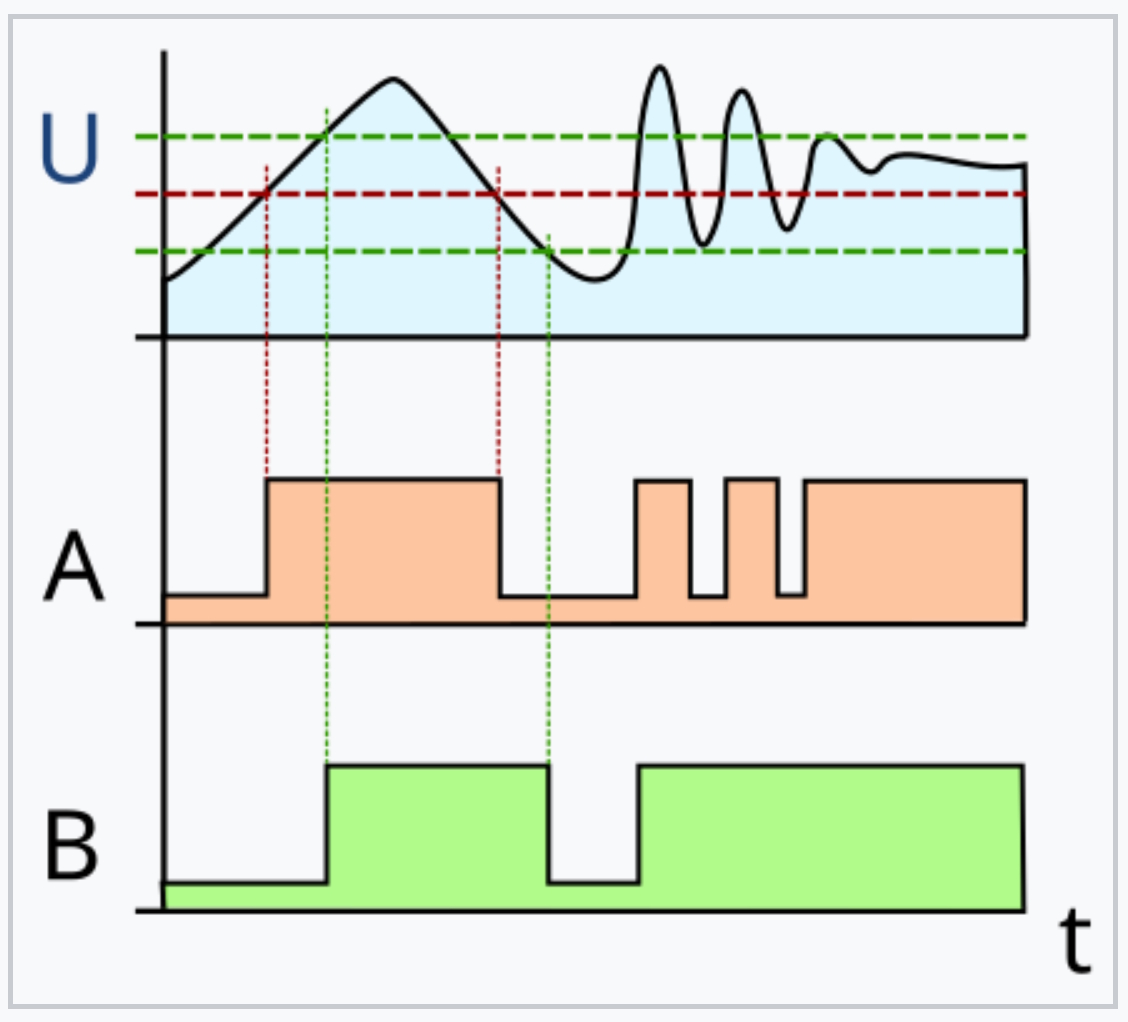
Positive feedback combined with hysteresis is a key enabler of Schmitt triggers. Positive feedback amplifies changes in the input signal, supporting rapid switching between states. That provides the low propagation delays needed by fast digital circuits and time-sensitive applications.
Hysteresis ensures that the device’s output depends on both the current input value and its past state, eliminating output changes due to small fluctuations near the threshold values. That enhances noise immunity.
What else are Schmitt triggers good for?
Schmitt triggers are versatile devices with applications beyond digital circuits. Three examples include:
- Sensors and signal processing applications use them to convert noisy or unstable analog outputs to clean and stable digital signals.
- Switches use them to debounce the output of mechanical contacts and clean up the multiple transitions that can result from contact bounce.
- Square wave generators that convert an analog sine wave or sawtooth signal into clean square waves for use in applications like timing circuits.
Summary
When used in industrial control systems, positive feedback can enhance response times but needs to be carefully managed to avoid instability. Schmitt triggers employ positive feedback and are used in digital systems, signal processing, and sensor applications to clean up noisy signals. Schmitt triggers are also used to convert analog signals into square waves for use in timing circuits.
References
Alternating Positive and Negative Feedback Control Model Based on Catastrophe Theories, MDPI mathematics
Feedback (positive and negative feedback), Toshiba
Feedback Systems, Electronics Tutorials
Introduction to Schmitt Trigger, Components101
Mastering Feedback Loops: Understanding Negative vs Positive Feedback, Shiny Planes
Positive feedback, Wikipedia
Positive Feedback Instability, Cadence
EEWorld Online related content
What’s a heavy-duty industrial connector?
What are the four types of machine learning, and what are they used for?
What’s the difference between GPUs and TPUs for AI processing?
How is Zephyr used for edge AI and sensors?
What’s the difference between mini delta ribbon and shrunk delta ribbon cable assemblies?


Leave a Reply