The defunct, obsolete LORAN navigation system is being revived with enhancements to overcome the potential performance and availability risks of GNSS.
Before GNSS and GPS, and before INS systems were available, another type of RF-based position-determining system was in wide use: LORAN.
Q: What is LORAN?
A: LORAN is short for LOng RAnge Navigation. LORAN, often written as Loran, is a hyperbolic radio navigation system developed in the United States during World War II. (Note that “hyperbolic” here refers to geometrical hyperbolas and should not be confused with hyperbole or “hype”, which is the use of exaggeration as a rhetorical device or figure of speech. Both have the same Greek root in rhetoric.)
Q: Was there only one iteration of this system?
A: No, it went through three major iterations, culminating in LORAN-C.
Q: How does LORAN operate? What’s the principle?
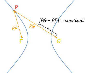
A: First, think back to high-school geometry and the world of conic sections: circles, ellipses, parabolas, and hyperbolas. The geometrical constructs can become intensely mathematical, of course. In simplest terms, the hyperbola is a curve defined by two focal points such that the absolute value of the difference of the distance between them is constant (Figure 1). Due to the definition, there are actually two mirror-image hyperbola curves for every pair of focal points and selected distance-difference constant value.
Q: This is all interesting, but where does this lead?
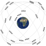
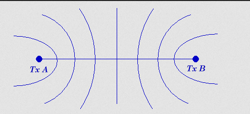
A: Imagine the hyperbola equation has many values of that constant. The result would be an array or set of hyperbolic curves (Figure 2).
Q: This may be interesting, but what does it have to do with navigation?
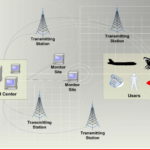
A: Again, in simplified terms, suppose the focal points are powerful transmitters that send coded, synchronized pulses. If you know the location of the transmitters and if you can accurately measure the time difference between the two signals at your receiver, you can determine the hyperbolic curve on which you are located.
Q: But this still does not indicate a specific position, only a position on a long hyperbolic arc. How is this reconciled?
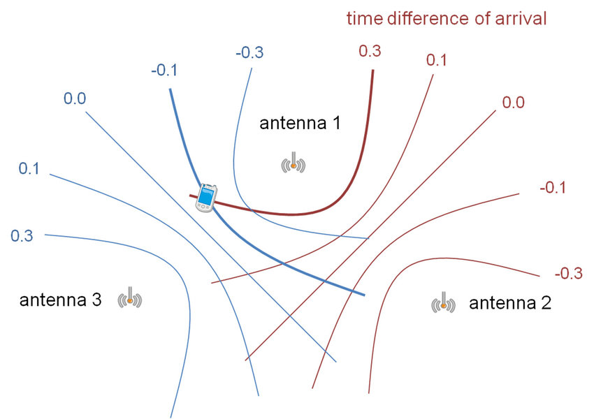
A: By adding more transmitter pairs (focal points) and thus independent sets of hyperbolic curves. The curves will cross, and a specific position can be determined (Figure 3), analogous to how the crossing of straight lines can determine a position.
Q: What is the order of the time difference, and how was it measured in the original LORAN system?
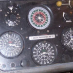
A: Depending on the distance between the measured signals and the location of the ship or aircraft receiver relative to them, it can be tens of microseconds to milliseconds. The first LORAN system used a triggered scan across a cathode-ray tube (CRT) with a calibrated time base. The trained operator would measure the screen distance between the two “pips” indicating different received signals (Figure 4).
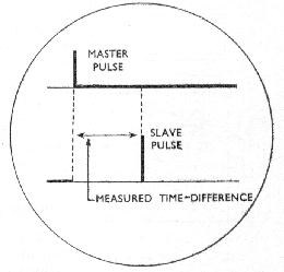
In reality, there would be several blips, clutter, image corruption, and unavoidable noise, so the operator needed some skill and practice; it was not a simple reading to make.
Q: Seems like a lot of work, is it?
A: It is, and with the vacuum-tube technology of the 1940s it took a lot of electronics, a big chassis, and a lot of electrical power to make it work. But it was worth it for what it provided when compared to the alternatives.
Q: What were the enhancements to LORAN?
A: For the original LORAN, eventually designated as LORAN-A, the enhancements included more transmitters, more accurate timing, and better receivers. Further, standardization between Navy and Air Force receivers allowed units to be swapped between them, resulting in enormous logistics and training savings.
Q: What sort of accuracy was possible with LORAN?
A: The early version of LORAN yielded accuracy on the order of several miles; subsequent upgrades reduced this by a factor of ten. But these results were achieved under best-case circumstances.
Q: What technical development was key to LORAN?
A: There were many, but critical to LORAN’s performance was its timing unit – a crystal oscillator that allowed a receiver on an aircraft, ship, or submarine to measure the difference between “master” (one transmitter) and “slave” radio pulses from other transmitters.
Q: What external factors would impede LORAN’s performance?
A: The primary factor which affected LORAN was signal propagation variations from the transmitters to the receiver. The signals can bounce off the layers of the atmosphere and can even bounce up and down from the ocean or land to the sky and back (Figure 5). This changes signal propagation timing and thus affects accuracy as well as the ability to make a crisp reading.
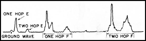
Q: What’s the difference between ground waves and sky waves?
A: LORAN was designed to allow skywaves to be used, and the resulting received signal was far more complex. The groundwave remained fairly sharp but could be received only at shorter distances and was primarily used during the day. At night, as many as thirty different skywaves might be received from a single transmitter, often overlapped in time, creating a complex return pattern. Since the pattern depended on the atmospherics between the transmitter and receiver, the received pattern was different for the two stations. One might receive a two-bounce skywave from one station at the same time as a three-bounce wave from another, making interpretation of the display quite difficult.
Q: What are some specifics on the LORAN transmitters?
A: LORAN stations were built in chains, with one primary and two secondaries (minimally, some chains were constituted of as many as five stations) typically separated by about 600 miles (970 km). Each pair broadcast on one of four frequencies:1.75, 1.85, 1.9, or 1.95 MHz. In any given location, receiving more than three stations at a time was common, so some other means of identifying the pairs were needed. LORAN adopted varying the pulse repetition frequency (PRF) for this task, with each station sending out a string of 40 pulses at either 33.3 or 25 pulses per second.
Q: Were these transmitters small and low power?
A: No, they broadcast at tens and hundreds of kilowatts. Many LORAN stations were in remote, inhospitable places. They required extensive infrastructure—personnel quarters, water and fuel tanks, communications equipment, and electrical generators. By the end of World War II, LORAN chains consisting of 72 stations provided navigation over 30 percent of the globe, mostly in the northern hemisphere. More than 70,000 receivers for aircraft, ships, and submarines had been built. By the height of the Cold War, coverage had extended to 70 percent of the Earth’s surface. The ionosphere and terrain limited daytime coverage, so LORAN was far more effective at night.
Q: How did LORAN end?
A: LORAN-C operation transitioned from the U.S. military to U.S. Coast Guard. Once the US GPS system was declared fully operational and approved, President Obama declared it obsolete In May 2009 and announced plans to terminate it.
But the LORAN story is not over. The next section looks at the enhancement to the deactivated, obsolete LORAN system to create eLORAN.
WTWH related content
eLORAN a terrestrial alternative to GPS
Quantum compasses and optical imaging for global positioning and navigation
Keeping hackers out of GPS receivers
GPS is a ubiquitous and problematic technology
Basics of GPS receivers
Time server GPS IC secures military comm, radar, networks
GPS anti-jamming/anti-spoofing antenna module sports 50 nsec latency
GNSS firewall software detects jamming/spoofing in real-time
Quartz crystals and oscillators, Part 2: Advanced crystals
Quartz crystals and oscillators, Part 1: Crystal basics
Fluxgate compasses, Part 2 – Issues and enhancements
Fluxgate Compasses, Part 1 – Context and principles
External References
General
- S. Department of Transportation, “What is Positioning, Navigation and Timing (PNT)?”
LORAN and eLORAN
- Smithsonian, Time and Navigation, “Why Was LORAN Such a Milestone?”
- Smithsonian, Time and Navigation, “Hyperbolic Systems”
- Wikipedia, “LORAN”
- Britannica, “loran”
- Web Pages Of Jerry Proc, “LORAN-A”
- Military & Aerospace Electronics, “Public-private partnership to launch eLORAN technology to back-up and accompany GPS”
- L National Bureau of Standards, Monograph 129, “The Development of LORAN-C Navigation and Timing” (a 1972 source document, 166 pages)
- GPS World, “GPS backup demonstration projects explained”
- UrsaNav, Inc., “eLoran System Definition and Signal Specification Tutorial” (47 pages PowerPoint, technically detailed)
- UrsaNav, Inc., “About Enhanced Loran” (brief overview)
- UrsaNav, Inc., “eLoran Points of Light” (16-page facts and myths – very useful)
- UrsaNav, Inc., “Resource Vault” (links to papers and tutorials)
- UrsaNav, Inc., “eLoran” (excellent two-page overview)
- S. Coast Guard, U.S. Department of Homeland Security, and Federal Aviation Administration, U.S. Department of Transportation, “Benefit-Cost Assessment Refresh The Use of eLORAN to Mitigate GPS Vulnerability for Positioning, Navigation, and Timing Services – Final Report (2009)” (37 pages with lots of bureaucratic content but also some nuggets)
- gov, “LORAN-C Infrastructure & E-LORAN”
- Spirent Communications, “Working With the Strengths and Weaknesses of Satellite Navigation Systems”
GNSS/GPS
- Bliley, “What’s The Differences Between the 5 GNSS Constellations?
- GNSS spoofing Septentrio, “OSNMA anti-spoofing technology now on PolaRx5 GNSS reference receivers” [Open Service Navigation Message Authentication]
Hyperbolas and math