IEEE 802.3cg defines these two Ethernet flavors, which deliver data and power over a single pair of wires.
In 2019, IEEE published 802.3cg, which added clauses 146 and 147 to its Ethernet 802.3 standard, which created 10Base-T1S (short reach) and 10Base-T1L (long reach). These two Ethernet flavors can serve vehicles and industry, respectively, where few wires take priority over high speed. Automotive Single-Pair Ethernet (SPE) 1000Base-T still has a place in vehicles for infotainment and assisted driving. Many automotive and industrial sensors don’t need high-speed links but need data and power.
The automotive industry has shown interest in 10Base-T1S because wires make up a significant percentage of a vehicle’s weight. Anything that reduces cabling helps with weight, cost, and energy efficiency. “Wiring is the third heaviest thing in the car,” said Craig Chabot, formerly of the University of New Hampshire Interoperability Lab (UNH-IOL) when EE World visited there in April 2024.

Vehicles currently use low-speed buses such as CAN, LIN, and FlexRay to carry data from sensors, while 1000Base-T high-speed Ethernet handles infotainment systems and serves as an overall communications backbone (Figure 1). The low-speed buses work well, and development on them continues, but there’s a movement to replace them with 10Base-T1S, thereby bringing Ethernet throughout the vehicle. You can use the same protocol stack regardless of the physical (PHY) layer. Connecting low-speed devices such as powertrain sensors using Ethernet instead of traditional buses brings all communications under the high-speed Ethernet backbone.
10Base-T1S devices communicate using half-duplex transmissions with optional full duplex. The bus supports up to eight devices communicating using 12.5 Mbaud at 1 VPP amplitude using 4B/5B encoding, hence a data throughput of 10 Mbps. Neither 10Base-T1S nor 10Base-T1L use forward-error correction (FEC).
In addition to transporting data, Ethernet can deliver small amounts of power over the data lines. It’s called Power over Data Lines (PoDL) or Single-pair Power over Ethernet (SPoE). Don’t confuse that with Power over Ethernet (PoE), which uses separate wire pairs for data and power.
Devices connected to a traditional Ethernet network need switches to manage transmissions and eliminate collisions. This is great for homes, offices, and industrial Ethernet, but switches take up space and add cost. They also add cabling because you need a dedicated eight-wire cable for each device, which is unacceptable in vehicles. 10Base-T1S eliminates switches.

10Base-T1S buses can handle up to eight nodes per line, connected through shielded or unshielded twisted pairs. That makes it suitable for zonal architectures within a vehicle. Figure 2 shows how a network might look.
Without a switch to manage transmissions, how can multiple Ethernet nodes play together without interfering with each other? Nodes stay in a high-Z state when they’re not talking to Node 0, the coordinator. “PHY-layer collision avoidance (PLCA) is the biggest thing about 10Base-T1S,” said UNH-IOL’s Jason Sisk during EE World’s lab visit.
PLCA operates at the PHY layer and does not interface with the medium access control (MAC) layer or any other layers. PLCA initiates when Node 0 sends a 20-bit beacon to all other nodes. IEEE 802.3cg defines a transmit-opportunity timer on each node, which the node resets upon receiving the beacon. The beacon includes a node ID that’s independent of its Ethernet MAC address. This begins a transmit cycle, letting each node transmit only during its turn, or opportunity, whenever the beacon’s ID matches that of a given drop. If a drop doesn’t have data to send, it remains in a high-Z state and doesn’t place a load on the bus. If a drop has data, it sends a commit signal while others wait their turn. “If you want to transmit,” said Sisk, “you’re in a 50 Ω configuration. If you’re listening, you’re in a high-Z state.” Figure 3 shows how the beacon, commit, and data transmissions fit within an Ethernet frame.

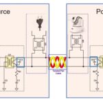
“If you have a trunk and two end nodes,” added Chabot, “you’ve got 100 Ω matched over a 100 Ω trunk.” “When you add a drop node, you’re looking at [two] 100 Ω [impedances] in parallel, so you have 50 Ω. In terms of reflections, the network needs proper termination. The length of the wire will affect that. Thus, you want an impedance match and how do you deal with that if the length of wire is different? How do you deal with the terminations in terms of a particular 10Base-T1S bus? Fortunately, the 10Base-T PHY ICs take care of that. There’s no need for anything more than optional termination resistors.”
Data, power, and test
Clearly, 10Base-T1S isn’t a simple point-to-point network, making it unique among Ethernet flavors. In addition to its multidrop capability, 10Base-T1S can also deliver power, though it has just two wires. That ability also exists in 10Base-T1L, a point-to-point network designed for industrial use. 10Base-T1L networks require switches to manage transmissions, the same as other Ethernet flavors.
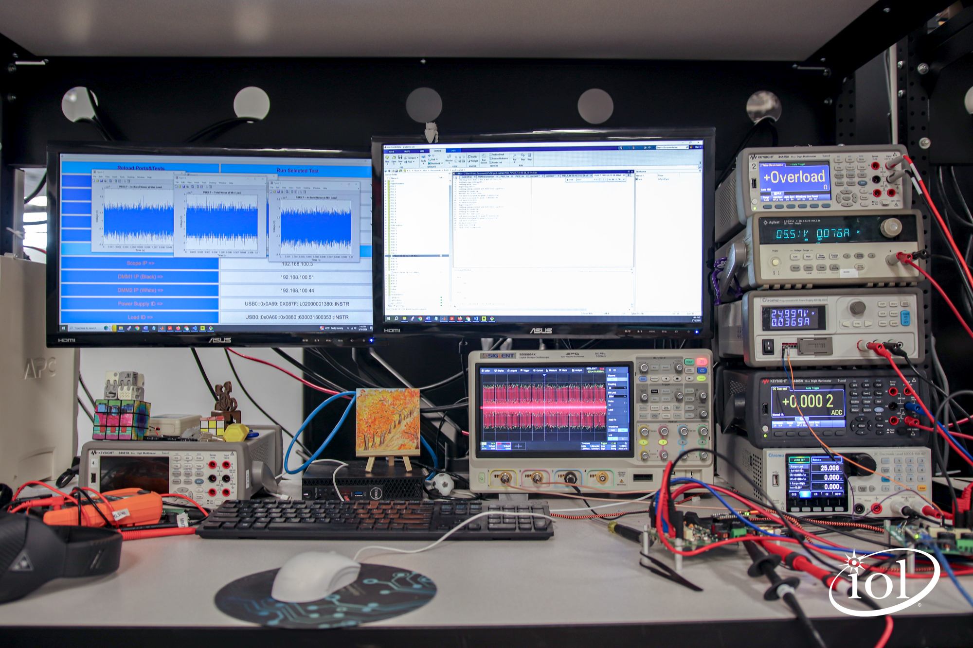
Because PoDL and SPoE use the same wire pairs to transmit data, power delivery needs to be negotiated between the source and loads. The UNH-IOL has developed test boards and software for testing communications and power delivery. Lab technician Marc Tausanovich demonstrated PoDL and SPoE tests. Figure 4 shows the test bench.
The test sequence begins with the Power Sourcing Equipment (PSE) pulling the line low, after which it looks for a load needing power. The remote load provides a pulse with a duration from 8.0 msec to 10.5 msec. Upon receiving the proper pulse, the source knows the classification of the load. For automotive 10Base-T1S, the class is known, and thus, the PoDL system operates using an unmanaged configuration. That’s as opposed to 10Base-T1L, where the needed voltage could be one of several classes. An oscilloscope captures the timing waveform and transfers it to a PC, where Matlab calculates the pulse width.
Noise on the load is particularly important when the same wires carry both power and data. Too much noise can cause data errors. Using AC coupling to remove the DC signal component, the oscilloscope captures the signal. Once the waveform data is on the PC, Matlab applies digital filters that let it measure in-band noise and total noise. The noise plots are visible on the monitor in Figure 4.

Figure 5 shows a close-up of PSE and network node test boards, each of which contains a 10Base-T-S PHY. The instrumentation consists of two power supplies, an electronic load, and a multimeter, which measure current. The top meter, which reads “Overload,” was not in use at the time.
10Base-T1S and its industrial cousin 10Base-T1L have the potential to simplify automotive and industrial digital communications. UNH-IOL’s Sisk noted that 10Base-T1S and PoDL will take time to find their way into vehicles. He noted that even with compliance and interoperability testing, automakers will still perform their own tests, which could take three years to complete.
Resources: 10Base-T1S Ethernet PHYs and test equipment
PHY:
Test equipment:
- 10Base-T1S Logic Analyzer / Protocol Analyzer, Acute
- QPHY-10Base-T1S oscilloscope software, Teledyne LeCroy
- AE6920T Automotive Ethernet Tx Test Software, Keysight Technologies
- PicoScope 3000E Series USB oscilloscope
References
“The Art of Networking (Series 10): Power over Data Line is Ready to Use,” Renesas.
Johnson, Mara, “PoDL and SPoE: What it Means for Industrial and Automotive Conformance Testing,” University of New Hampshire.
Chabot, Craig, “The Evolution of Power for Single Pair Ethernet,” University of New Hampshire.
“Will Ethernet cancel CAN? ” Avnet.
“What is 10Base-T1S Automotive Ethernet?” Teledyne LeCroy.
Hurley, Fionn, “Why 10BASE-T1S Is the Missing Ethernet Link for Automotive Communications,” Analog Devices.
“Introduction to 10BASE-T1S Automotive Ethernet Test Standards,” Granite River Labs.

Leave a Reply