• Skip to primary navigation
  • Skip to main content
  • Skip to primary sidebar
  • Skip to footer

Microcontroller Tips

Microcontroller engineering resources, new microcontroller products and electronics engineering news

  • Products
    • 8-bit
    • 16-bit
    • 32-bit
    • 64-bit
  • Applications
    • 5G
    • Automotive
    • Connectivity
    • Consumer Electronics
    • EV Engineering
    • Industrial
    • IoT
    • Medical
    • Security
    • Telecommunications
    • Wearables
    • Wireless
  • Learn
    • eBooks / Tech Tips
    • EE Training Days
    • FAQs
    • Learning Center
    • Tech Toolboxes
    • Webinars/Digital Events
  • Resources
    • Design Guide Library
    • DesignFast
    • LEAP Awards
    • Podcasts
    • White Papers
  • Videos
    • EE Videos & Interviews
    • Teardown Videos
  • EE Forums
    • EDABoard.com
    • Electro-Tech-Online.com
  • Engineering Training Days
  • Advertise
  • Subscribe

What inductor characteristics are needed for PoDL in Single-Pair Ethernet?

September 11, 2023 By Jeff Shepard Leave a Comment

Basic Single-Pair Ethernet (SPE) requires at least a common mode inductor (CMI). When power over data line (PoDL) functionality is added, so is a differential mode inductor (DMI) and sometimes an isolation transformer. These magnetic elements interact and can reduce SPE performance. Correctly specifying them is important to ensure efficient operation and reliable data transfer.

PoDL is designed for point-to-point power delivery and does not support multidrop power delivery. The PoDL system consists of the power sourcing equipment (PSE) and the powered device (PD) (Figure 1). IEEE 802.3bu defines four types of PSEs, including ten classes rated for 12, 24, and 48 Vdc unregulated and regulated power delivery. IEEE 802.3cg added a new PSE type and added 30 V and 58 V classes, bringing the total to 16 classes. Optimized coupling of the power onto the data channel is critical; PoDL can affect the channel through the coupling network in several ways:

  • The DMI and its interaction with the transformer can affect mode conversion and return loss.
  • Power supply noise, dv/dt, and di/dt can reduce data integrity.
Figure 1. A PoDL application includes the power source and the powered device (Image: Würth Elektronik).

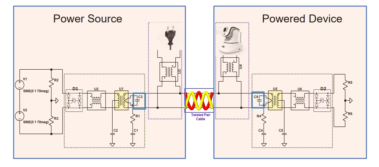
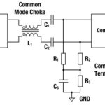
The coupling-decoupling network (CDN) that connects the SPE electronics to the cabling uses the CMI (U2 and U6 in Figure 1) to reduce common mode interference on the differential signals. The CMI can be placed before or after the coupling circuit. If the CMI is after the coupling circuit, the power current flows through it, and the CMI can be used to improve the symmetry of the power injection. If the CMI is before the coupling circuit, the power current does not flow through it, and the same CMI can be used for PoDL and non-PoDL applications.

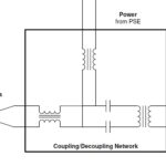
The transformer (U1 and U5 in Figure 1) provides isolation for safety-critical applications, and the isolation rating is application-dependent. The DMI (U3 and U4 in Figure 1) must have a saturation current as defined for the deployed power class (there are 16 power classes). The isolation transformer’s inductance is parallel to the DMI’s inductance. Clause 104 requires that the total inductance be high enough to minimize loading at frequencies of 7.5 MHz or higher and specifies a maximum 25% signal droop.

Figure 2. 470 µH shielded wire wound inductor rated for 1,810 mA and 250 mΩ with a saturation current of 2,300 mA suitable for use in PoDL class 15 applications (Image: TDK).

In addition, the higher current defined for the highest power class, class 15, requires a different architecture. In this case, a line-side injection can be used, and the DMI can be placed between the CMI and the connector. The CMI can be smaller since it does not have to handle the transmitted power, only the data signals.

SMD DMIs
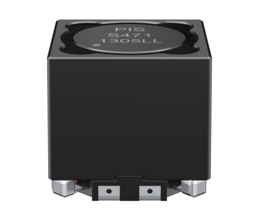
Specially optimized DMIs are available for PoDL applications. One DMI product family includes devices that cover power classes 10 to 15 for industrial applications as defined in 802.3cg. They feature saturation currents from 360 to 2,100 mA and are designed for operation from -40 to +125 °C. Another option is a part intended for use in class 15 power applications as a single inductor for noise suppression and smoothing of currents with a saturation current of 2,300 mA. (Figure 2).

Summary
SPE requires a CMI. When PoDL is implemented, a DMI and an isolation transformer are also needed. Potential interactions between these magnetic components can reduce system performance and demand careful attention when they are being specified to achieve reliable data transfers and power efficiency.

References
A Quick Walk Around the Block with PoDL, IEEE
How to Implement an IEEE 802.3cg or 802.3bu-Compliant PoDL PSE, Texas Instruments
Power over Data Line is ready to use, Renesas

You may also like:


  • What’s the difference between an SPE isolation inductor and a…

  • How do common mode inductors work in Single-Pair Ethernet?

  • How to specify differential mode inductors for Single-Pair Ethernet?

  • What is Single-Pair Ethernet and PoDL?

  • Connector standard helps pave the way to the IIoT

Filed Under: Ethernet, FAQ, Featured Tagged With: FAQ

Reader Interactions

Leave a Reply Cancel reply

Your email address will not be published. Required fields are marked *

Primary Sidebar

Featured Contributions

Five challenges for developing next-generation ADAS and autonomous vehicles

Securing IoT devices against quantum computing risks

RISC-V implementation strategies for certification of safety-critical systems

What’s new with Matter: how Matter 1.4 is reshaping interoperability and energy management

Edge AI: Revolutionizing real-time data processing and automation

More Featured Contributions

EE TECH TOOLBOX

“ee
Tech Toolbox: Internet of Things
Explore practical strategies for minimizing attack surfaces, managing memory efficiently, and securing firmware. Download now to ensure your IoT implementations remain secure, efficient, and future-ready.

EE Learning Center

EE Learning Center

EE ENGINEERING TRAINING DAYS

engineering
“bills
“microcontroller
EXPAND YOUR KNOWLEDGE AND STAY CONNECTED
Get the latest info on technologies, tools and strategies for EE professionals.

RSS Current EDABoard.com discussions

  • Editing posts
  • avoiding mixer compression when acting as a phase detector
  • Crude Powerline FSK comms literally shorts the power bus at a certain frequency?
  • ISL8117 buck converter blowing up
  • audio transformers impedance

RSS Current Electro-Tech-Online.com Discussions

  • RS485 bus: common ground wire needed or not?
  • Kawai KDP 80 Electronic Piano Dead
  • Good Eats
  • What part is this marked .AC ?
  • Photo interrupter Connections

DesignFast

Design Fast Logo
Component Selection Made Simple.

Try it Today
design fast globle

Footer

Microcontroller Tips

EE World Online Network

  • 5G Technology World
  • EE World Online
  • Engineers Garage
  • Analog IC Tips
  • Battery Power Tips
  • Connector Tips
  • DesignFast
  • EDA Board Forums
  • Electro Tech Online Forums
  • EV Engineering
  • Power Electronic Tips
  • Sensor Tips
  • Test and Measurement Tips

Microcontroller Tips

  • Subscribe to our newsletter
  • Advertise with us
  • Contact us
  • About us

Copyright © 2025 · WTWH Media LLC and its licensors. All rights reserved.
The material on this site may not be reproduced, distributed, transmitted, cached or otherwise used, except with the prior written permission of WTWH Media.

Privacy Policy