The relentless march of technological progress has given engineers increasingly smaller and more energy efficient microcontrollers to use in their designs. These benefits do come with a cost, however. Physically smaller packages have less room for I/O pins meaning fewer peripheral components can interface with the microcontroller itself. Fewer peripherals means less functionality which tends not to be a desirable tradeoff.
Even when utilizing bus-based protocols such as I2C or SPI, there is often a need for each external integrated circuit to have a pin dedicated for chip select or output enable (often notated as CS or OE on schematics, or /CS and /OE for active low variations). After accounting for power, ground, reset, and the I2C pins on a small 8-pin chip like an ATtiny85, a design might at most interface with three external peripherals using the remaining I/O pins. Of course, one option would be to explore larger chips within the same microcontroller family. Depending on component availability or design constraints this might not be a possible option. Another possibility is to incorporate an additional circuit that sits between the microcontroller and the various external components. Circuits such as multiplexers, demultiplexers, and decoders come in a variety of packages and voltage levels so they can be incorporated into a board layout with relative ease.
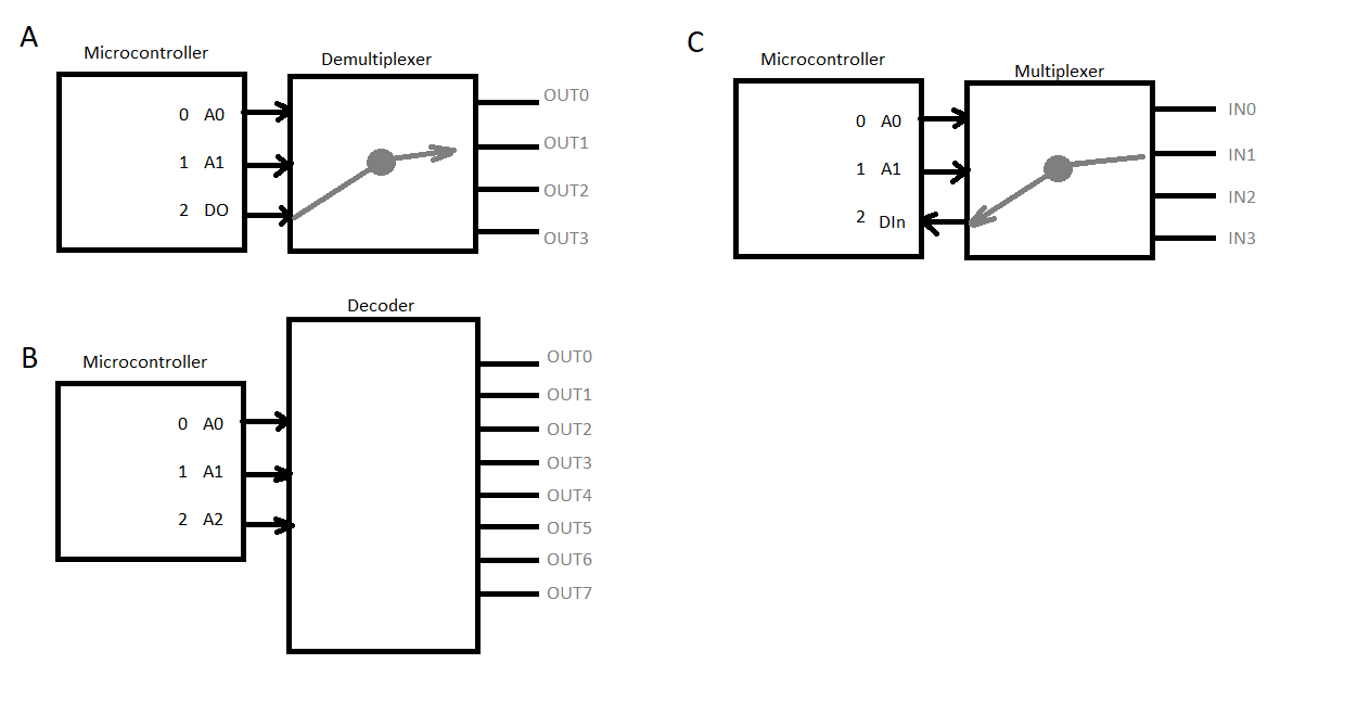
With a demultiplexer we can take two of the microcontroller’s I/O pins and turn them into address pins (for example A1 and A0). The third pin serves as a digital output whose signal then can be redirected to up to four external peripheral components by toggling the address pins into one of four states including < A1:A0 > = 00, 01, 10, and 11.
If there is no need for a controllable output signal then it might be more desirable to instead use a decoder. With a decoder those same three pins (the two address pins and the digital output pin) could be instead used to interface with eight peripheral components thanks to the power of binary arithmetic (23 = 8). This is extremely useful in situations such as handling chip select or output enable pins of external ICs where those pins only need to drive to the source voltage or ground. Inverters can be placed on the output of the active high decoders to handle chips that required active low enables. Practically speaking 2:4 and 3:8 decoders are most common in discrete packages. However, it is possible to cascade multiple discrete decoders into larger networks as needed. Be careful not to go too large as problems may arise from fan-in and fan-out. Issues that could arise include slowed response times or even voltage levels dropping below defined logic levels.
Lastly, it is also possible to employ a similar concept for inputs being fed into a microcontroller from external devices such as sensors or switches. Instead of a demultiplexer, a multiplexer can be employed to funnel multiple outputs into a single input pin. Special care must be placed by the firmware designer to ensure the logic is correct when handling the different inputs and the associated variables that represent them in code. Be aware that decoder, multiplexer, and demultiplexer chips may have output enable (OE) pins themselves. Depending on the circuit design these pins can be hardwired to ground or source voltage so a microcontroller pin need not be used. The tradeoff being the chip is always on which may or may not be desired. Otherwise, a microcontroller pin must be budgeted for in the design.
I would add shift registers to the list. Cheap 74HC595 chips or development boards, for example.
Hii what if we have to control every single pin. in shift register we shift data from one pin to other.