• Skip to primary navigation
  • Skip to main content
  • Skip to primary sidebar
  • Skip to footer

Microcontroller Tips

Microcontroller engineering resources, new microcontroller products and electronics engineering news

  • Products
    • 8-bit
    • 16-bit
    • 32-bit
    • 64-bit
  • Applications
    • 5G
    • Automotive
    • Connectivity
    • Consumer Electronics
    • EV Engineering
    • Industrial
    • IoT
    • Medical
    • Security
    • Telecommunications
    • Wearables
    • Wireless
  • Learn
    • eBooks / Tech Tips
    • EE Training Days
    • FAQs
    • Learning Center
    • Tech Toolboxes
    • Webinars/Digital Events
  • Resources
    • Design Guide Library
    • DesignFast
    • LEAP Awards
    • Podcasts
    • White Papers
  • Videos
    • EE Videos & Interviews
    • Teardown Videos
  • EE Forums
    • EDABoard.com
    • Electro-Tech-Online.com
  • Engineering Training Days
  • Advertise
  • Subscribe

What does an eye diagram or eye pattern on an oscilloscope mean?

March 10, 2017 By Scott Thornton Leave a Comment

Figure 1: Eye diagrams help determine at a glance the health of a digital signal. As a diagnostic tool, it shows the performance in aggregate, so locating which edge is associated with an artifact is difficult. (Source: Author markup.)

Eye diagrams are a quick, visual means of identifying signal integrity issues before moving on to more refined analysis. They help with the effective analysis of serial data and offer both qualitative and quantitative insight regarding the data communications signal path itself and what might be affecting signal integrity.

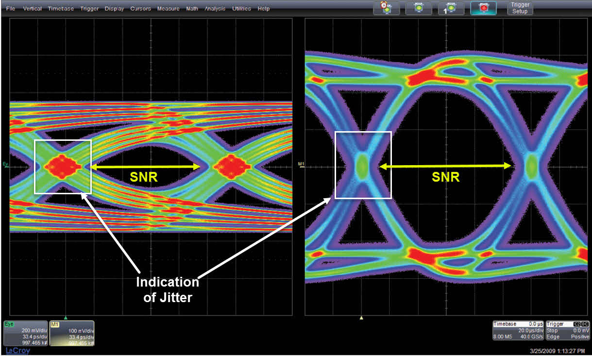
Circuit designs that reach the prototype stage may have been simulated before testing a PCB prototype. However, every design gets bench-tested before going on to higher volume production. In developing and interfacing with high-speed serial communications such as USB, you will want to use an oscilloscope to troubleshoot and analyze serial data. Viewing eye diagrams can help find crosstalk, electromagnetic interference (EMI), signal loss, and other phenomena affecting signal integrity. The term “eye” refers to the pattern on the oscilloscope that looks like an eye. The bigger the opening of the “eye,” the better the signal-to-noise ratio. The general amount of jitter can be seen in the crossing.

Figure 2: Eye diagram, or eye pattern showing constant 0 and 1 levels and transitions from 0 to 1, 1 to 0, and from 0 to 1 to 0 as well as 1 to 0 to 1. (Source: Wikipedia, credit: Gmoose1.)

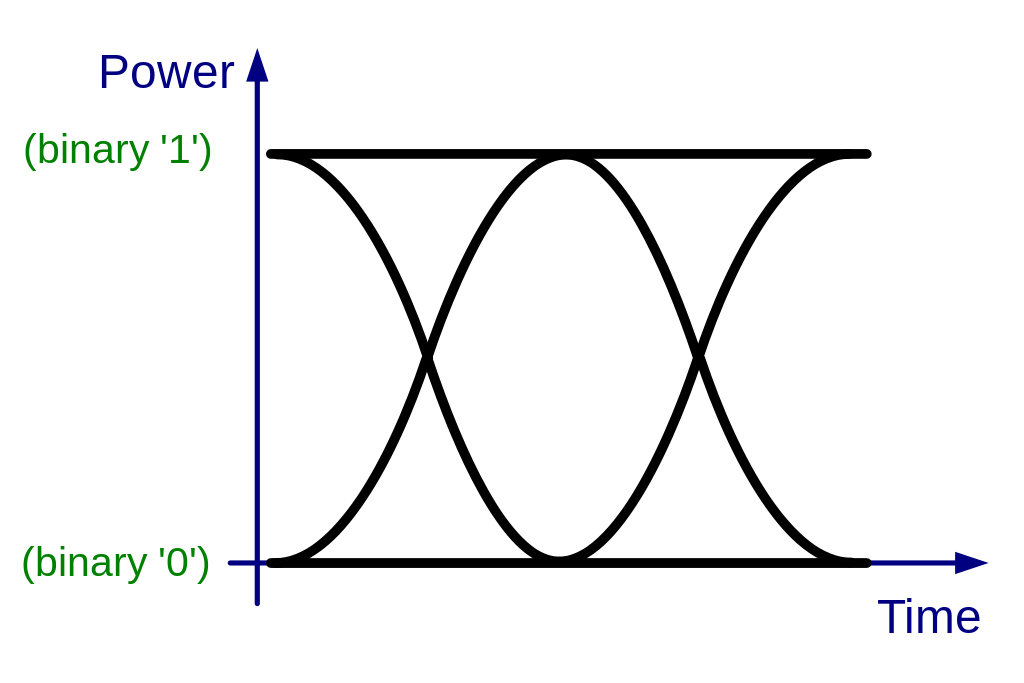
An eye diagram is a pattern shown on an oscilloscope that depicts a fuller view of what a digital signal stream looks like from a more holistic viewpoint, one could say. What’s actually happening is that the oscilloscope is receiving, or sampling, a digital signal (a stream of step functions that represent 0s and 1s in varying patterns.) The oscilloscope samples little chunks of the received signal and displays them all, superimposed, on the screen. The result looks like an eye on the oscilloscope screen. The scope accumulates the chunks and displays the cumulative effect of the stream of 0s and 1s (step functions) on the screen. Every bit pattern it captures is superimposed on the oscilloscope’s screen.

The eye diagram’s purpose is to witness the health of the signal integrity at a glance. You can easily see the noise margins of the data signal with an eye diagram. Noise margin refers to the amount by which the signal for 0 or 1 exceeds ideal boundaries but is still within an acceptable range. The data clock defines an eye diagram’s unit interval or bit period. As mentioned above, the eye diagram displays all of the values, which are in variable positions due to noise or other factors, that a digital signal takes on during a bit period.  Noise and other factors can make the digital signal deviate from a train of perfect step functions in a stream of 0s and 1s, and this is cumulatively displayed in aggregate in the eye diagram. A closed eye indicates a noisy, unpredictable signal.

Eye diagrams are great for a quick high-level diagnostic, but they do not make good diagnostic tools beyond telling you if it looks good…or not. The performance of the digital signal is shown in aggregate, which makes it difficult to diagnose which edge is associated with a specific artifact. Older oscilloscopes show the eye diagram in one color. Modern oscilloscopes help with diagnostics somewhat by at least showing signals in different colors corresponding to frequency and voltage level on a per-pixel basis.


You may also like:


  • What is the automotive SENT protocol?

  • How is HIL testing used for onboard EV chargers?

  • JavaScript-based exerciser verifies hardware/software integration tasks

Filed Under: FAQ, Featured Tagged With: basics, eye diagram, FAQ, teledynelecroy

Reader Interactions

Leave a Reply Cancel reply

Your email address will not be published. Required fields are marked *

Primary Sidebar

Featured Contributions

Five challenges for developing next-generation ADAS and autonomous vehicles

Securing IoT devices against quantum computing risks

RISC-V implementation strategies for certification of safety-critical systems

What’s new with Matter: how Matter 1.4 is reshaping interoperability and energy management

Edge AI: Revolutionizing real-time data processing and automation

More Featured Contributions

EE TECH TOOLBOX

“ee
Tech Toolbox: 5G Technology
This Tech Toolbox covers the basics of 5G technology plus a story about how engineers designed and built a prototype DSL router mostly from old cellphone parts. Download this first 5G/wired/wireless communications Tech Toolbox to learn more!

EE Learning Center

EE Learning Center

EE ENGINEERING TRAINING DAYS

engineering
“bills
“microcontroller
EXPAND YOUR KNOWLEDGE AND STAY CONNECTED
Get the latest info on technologies, tools and strategies for EE professionals.

DesignFast

Design Fast Logo
Component Selection Made Simple.

Try it Today
design fast globle

Footer

Microcontroller Tips

EE World Online Network

  • 5G Technology World
  • EE World Online
  • Engineers Garage
  • Analog IC Tips
  • Battery Power Tips
  • Connector Tips
  • DesignFast
  • EDA Board Forums
  • Electro Tech Online Forums
  • EV Engineering
  • Power Electronic Tips
  • Sensor Tips
  • Test and Measurement Tips

Microcontroller Tips

  • Subscribe to our newsletter
  • Advertise with us
  • Contact us
  • About us

Copyright © 2025 · WTWH Media LLC and its licensors. All rights reserved.
The material on this site may not be reproduced, distributed, transmitted, cached or otherwise used, except with the prior written permission of WTWH Media.

Privacy Policy