• Skip to primary navigation
  • Skip to main content
  • Skip to primary sidebar
  • Skip to footer

Microcontroller Tips

Microcontroller engineering resources, new microcontroller products and electronics engineering news

  • Products
    • 8-bit
    • 16-bit
    • 32-bit
    • 64-bit
  • Applications
    • 5G
    • Automotive
    • Connectivity
    • Consumer Electronics
    • EV Engineering
    • Industrial
    • IoT
    • Medical
    • Security
    • Telecommunications
    • Wearables
    • Wireless
  • Learn
    • eBooks / Tech Tips
    • EE Training Days
    • FAQs
    • Learning Center
    • Tech Toolboxes
    • Webinars/Digital Events
  • Resources
    • Design Guide Library
    • DesignFast
    • LEAP Awards
    • Podcasts
    • White Papers
  • Videos
    • EE Videos & Interviews
    • Teardown Videos
  • EE Forums
    • EDABoard.com
    • Electro-Tech-Online.com
  • Engineering Training Days
  • Advertise
  • Subscribe

How to specify differential mode inductors for Single-Pair Ethernet?

August 25, 2023 By Jeff Shepard Leave a Comment

Differential mode inductors (DMIs) are important components for the Power over Data Line (PoDL) and the related Single-Pair Power over Ethernet (SPoE) standards.

This article begins by reviewing where DMIs fit into Single-Pair Ethernet (SPE) and then compares PoDL and SPoE implementations and application targets.

Coupling and decoupling
DMIs play an important role in SPE coupling and decoupling networks (CDNs). The CDN has three magnetic components: a common mode inductor (CMI), an isolation transformer, and the DMI. The isolation transformer is an optional component used in safety-critical, PoDL, and SPoE designs, while the CMI is included in all SPE designs (Figure 1).

Figure 1. An SPE coupling/decoupling network consists of a CMI (bottom left), an optional DMI (top) for PoDL and SPoE designs, and an optional isolation transformer (right) for safety-critical applications (Image: Texas Instruments).

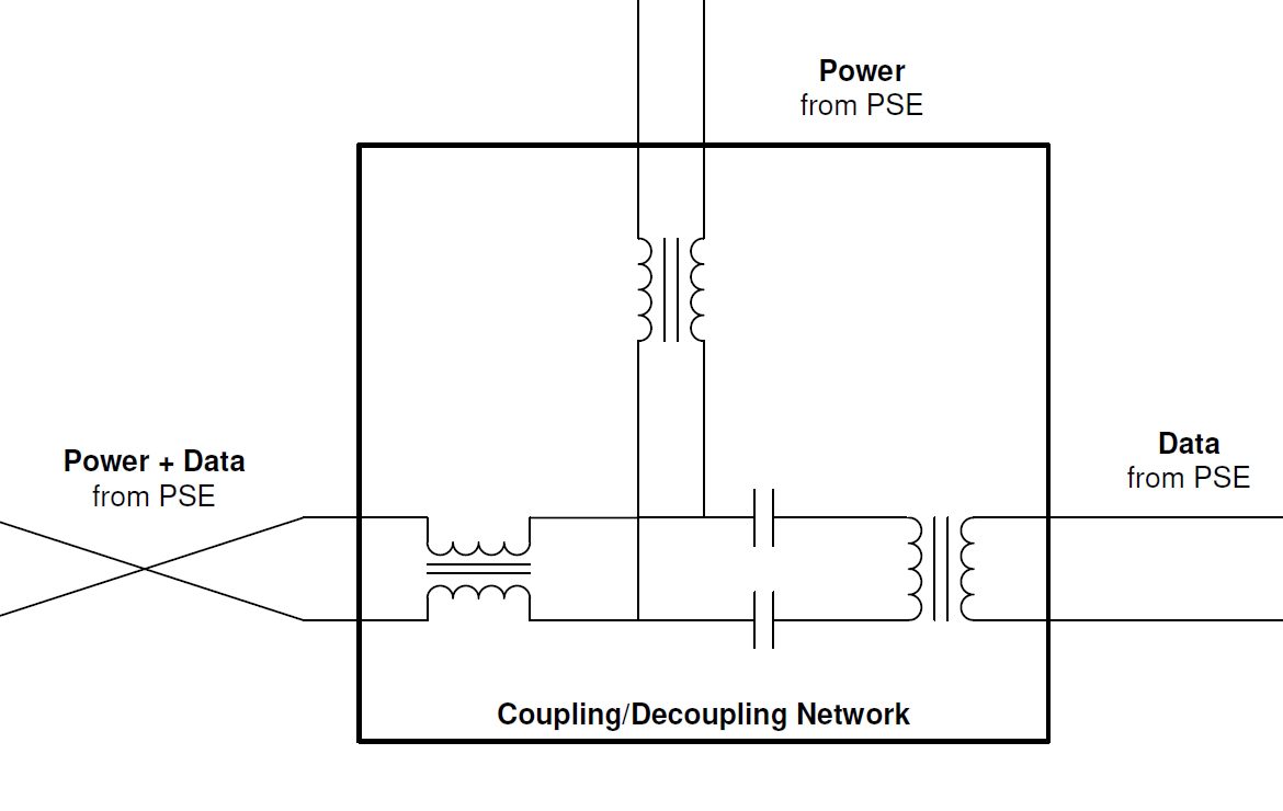
In a simple design, the SPE cable brings data into the device. In PoDL and SPoE designs, the cable carries both power and data. In both cases, the CMI, together with a couple of capacitors, suppresses common-mode noise. The common mode noise must be filtered while maintaining the integrity of the differential signal.

The transformer inductance and DMI inductance interact, as shown in the example in the next section on PoDL vs SPoE. The DMI requires a low direct current resistance (DCR) for efficient operation. Typical DCR values range from 360 mA to 2100 mA, depending on the powered device (PD) class of the design. In addition, the DMI’s inductance should be high enough to prevent excessive damping of the data.

PoDL vs SPoE
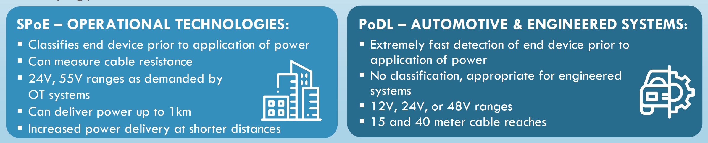
SPoE is like PoDL but targets different use cases. In both standards, power and data are separated via inductive (DC) coupling and transformer (AC) coupling, respectively. In both standards, power is extracted by the DMI. Like the CMI, it must have a maximum current rating appropriate for the PD class in use and low DC resistance to minimize power loss.

SPoE is an extension of the original PoDL standard. PoDL was specifically designed for use in automotive networks and other embedded systems. SPoE adds power classes 10 to 15 designed for use in industrial networks and building automation systems operating on either 24 Vdc or 55 Vdc power (Table 1).

Table 1. SPoE is an extension of the original automotive PoDL specification and is targeted at industrial networks and operational technologies like building automation (Table: Ethernet Alliance).

In PoDL and SPoE, the inductance of the isolation transformer is parallel to the inductance of the DMI. The standard requires that the total inductance must be high enough to minimize loading at frequencies of 7.5 MHz or higher. IEEE 802.3dd-2022 specifies a maximum signal drop of 25%. For example, in one design a DMI with an inductance of 220 µH is used with a transformer that has an inductance of 2200 µH resulting in a total inductance of 200 µH and a maximum signal drop of 10%, more than adequate to meet the 25% requirement.

Summary
DMIs are important elements in the CDLs of PoDL and SPoE designs. The DMI needs a low DCR to enable efficient operation and a high enough inductance to prevent data damping. In addition, the DMI’s inductance is in parallel with the isolation transformer’s inductance, and the combined inductance must be high enough to limit signal droop to 25% or less for signals of 7.5 MHz and higher.

References
10BASE-T1L Field Device Development Platform with Class 12 and 13 SPoE, Analog Devices
IEEE 802.3cg 10BASE-T1L Power over Data Lines Powered Device Design, Texas Instruments
Single-pair power over Ethernet, Ethernet Alliance

You may also like:


  • What is Single-Pair Ethernet and PoDL?

  • August 2023 Issue: Automotive & Transportation Electronics

  • How do MCUs support automotive infotainment systems?

  • How do the seven types of V2X connectivity work?

  • What’s different about MCUs for use in vehicle networking?

Filed Under: Applications, Connectivity, Ethernet, FAQ, Featured Tagged With: FAQ

Reader Interactions

Leave a Reply Cancel reply

Your email address will not be published. Required fields are marked *

Primary Sidebar

Featured Contributions

Five challenges for developing next-generation ADAS and autonomous vehicles

Securing IoT devices against quantum computing risks

RISC-V implementation strategies for certification of safety-critical systems

What’s new with Matter: how Matter 1.4 is reshaping interoperability and energy management

Edge AI: Revolutionizing real-time data processing and automation

More Featured Contributions

EE TECH TOOLBOX

“ee
Tech Toolbox: 5G Technology
This Tech Toolbox covers the basics of 5G technology plus a story about how engineers designed and built a prototype DSL router mostly from old cellphone parts. Download this first 5G/wired/wireless communications Tech Toolbox to learn more!

EE Learning Center

EE Learning Center

EE ENGINEERING TRAINING DAYS

engineering
“bills
“microcontroller
EXPAND YOUR KNOWLEDGE AND STAY CONNECTED
Get the latest info on technologies, tools and strategies for EE professionals.

DesignFast

Design Fast Logo
Component Selection Made Simple.

Try it Today
design fast globle

Footer

Microcontroller Tips

EE World Online Network

  • 5G Technology World
  • EE World Online
  • Engineers Garage
  • Analog IC Tips
  • Battery Power Tips
  • Connector Tips
  • DesignFast
  • EDA Board Forums
  • Electro Tech Online Forums
  • EV Engineering
  • Power Electronic Tips
  • Sensor Tips
  • Test and Measurement Tips

Microcontroller Tips

  • Subscribe to our newsletter
  • Advertise with us
  • Contact us
  • About us

Copyright © 2025 · WTWH Media LLC and its licensors. All rights reserved.
The material on this site may not be reproduced, distributed, transmitted, cached or otherwise used, except with the prior written permission of WTWH Media.

Privacy Policy