LiDAR systems and ToF techniques are critical to providing self-driving cars with a detailed picture of the surrounding and is used in many research applications as well. This is part two of a four-part series on LiDAR systems and ToF techniques.
Just as for radar and sonar, the LiDAR concept is simple but the execution is difficult; light and photons are very different in behavior and management than RF or acoustic energy. Still, LiDAR works well, and a light-based system can provide both precise distance and angular resolution due to the short wavelength of light among other factors.
The LiDAR system begins with a laser diode or LED which is directed to emit infrared light (Figure 1). Direct ToF uses short pulses of light, and measures the time until each pulse returns to the sensor to measure the distance to an object. Indirect ToF sensors emit a continuous wave of modulated light. A photoreceptor senses any reflections, and the timing and phase of the reflected light are used to calculate the distance to the object which produced the reflection. For direct ToF, the pulses are typically several nanoseconds wide. Shorter pulses give higher resolution but have less energy and thus the received reflection has inferior sign/noise ratio (SNR); that’s one the many tradeoffs.
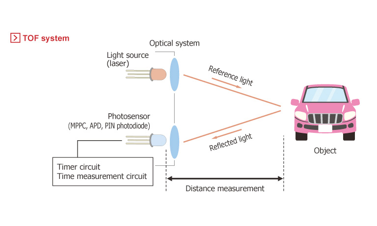
That’s the principle of LiDAR. In reality, precise measurement of the reflection timing (and phase) with the needed accuracy and resolution is difficult. In burst mode, the LiDAR instrument fires rapid pulses of light, with a rate of 100 kHz and more. In continuous, the timing resolution is enhanced by matching the phase of the reflection with the phase of the source waveform.
More than just a simple reflection
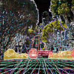
Eventually, the LiDAR system builds up a complex map called a point cloud of the surface it is measuring, Figure 2a and 2b. It is important to understand that a LiDAR system goes far beyond just a basic pulse/reflection mode of sensing “is something ahead, and if so, how far ahead?”
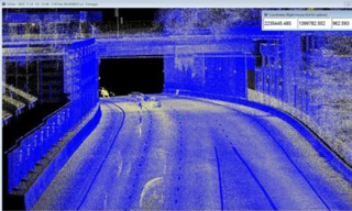
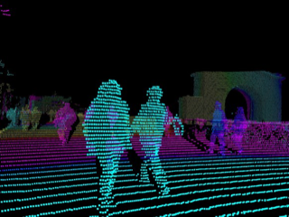
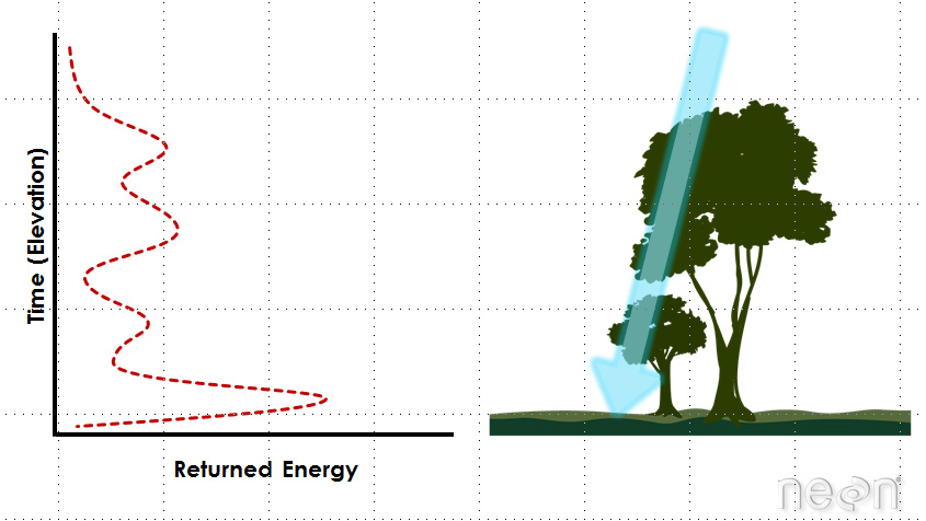
Instead, the role of a LiDAR system is to provide the raw data so the car’s image processors can create that full 3D point cloud based on the reflections. This is done by directing the emitted beam in a scan pattern, using the reflections to create an image which captures the surroundings with details, depth, and clarity. Even scanning a single object such as a tree shows the variation in reflections that will be developed and used (Figure 3).
This point cloud can then be further integrated by the vehicle’s processors to provide a detailed sense of the surroundings in all directions, and at what distances. Creating this detailed image in real time requires a significant amount of dedicated, specialized computational effort after the LiDAR front-end capture, due to both the real-time nature of the situation and the huge amounts of reflection data (points) being returned.
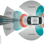
The processing algorithms transform the huge amounts raw reflection data into a volume and vector map relative to the vehicle’s position, speed, and direction. The resultant image insight is used for object identification, motion vectors, collision prediction, and collision avoidance. The algorithms are designed to define the image in different zones; typically, a medium distance of about 20 to 40 meters to the sides for angular imaging, and between 150 to 200 meters for front-and-rear long-distance imaging.
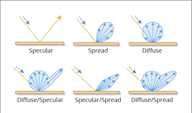
Keep in mind that the reflection created by the surface are not simple, as they would be from a mirror. Instead, there are indirect reflections, off-angle reflections from other emitter pulses, multiple reflections where the impinging photons hit one surface, bounce to another and return after the primary reflection, diffused reflections from rough or irregular surfaces, and more. The LiDAR/ToF concept is simple but takes a lot of front-end enhancements to maximize SNR and minimize distortion as well as algorithm advances to extract a viable and correct image. Matte and irregular surfaces can cause significant complications for ToF measurements, as it can be difficult for the sensor to understand which photons came from where. In confined spaces, photons can also bounce off walls and other objects, further confusing the measured distance (Figure 4).
These challenges are not new or unique to LiDAR. They have close analogies in multipath of RF signals, ground clutter as seen by radar, ultrasound imaging, fingertip-based optical blood-oxygen (SpO2) measurements, and many other real-world issues. In practice, such interference, scattering, and diffusion– whether acoustic, RF, or optical – are challenges to seeing what’s out there and getting details about the surroundings. These issues have been studied extensively, with math-intensive analysis along with practical experience. This body of knowledge is expanding with the millions of miles of road trips that experimental and test autonomous vehicles are providing.
Part 3 looks at LiDAR system optical emitters and sensors, as well as the scanning arrangement where needed.
EE World References
- Autonomous vehicle sees with LiDAR eyes
- A better way to measure lidar
- How can picture-like images be obtained from LiDAR?
- Doppler Lidar for Autonomous Cars Excels in Real-World Tests
- At Autonomous Vehicle Sensors Conference: Upstart Lidar Companies Face Off
- GaN FET driver excels at solid-state light detection and LiDAR apps
- What advanced sensing techniques are used to find lost treasures? Part 5: LiDAR
- The Future Of LIDAR For Automotive Applications
- LiDAR: How The Next Generation Of Radar Mapping Works
- Vacuum tubes we still (have to) use: The photomultiplier tube, Part 1
- Vacuum tubes we still (have to) use: The photomultiplier tube, Part 2
External References
- IEEE Spectrum, “Lidar-on-a-Chip: Scan Quickly, Scan Cheap”
- Tech Briefs, “Real-Time LiDAR Signal Processing FPGA Modules”
- NASA, “A Survey of LIDAR Technology and its Use in Spacecraft Relative Navigation”
- Laser Focus World, “Lidar advances drive success of autonomous vehicles“
- DARPA, “SWEEPER Demonstrates Wide-Angle Optical Phased Array Technology”
- NOAA, “What is LIDAR?”
- Terabee, “Time of Flight principle”
- Terabee, “A Brief Introduction to Time-of-Flight Sensing: Part 1 – The Basics”
- AMS AG, “Time-of-Flight Sensing”
- All About Circuits, “How Do Time of Flight Sensors (ToF) Work? A Look at ToF 3D Cameras”
- Texas Instruments, “ToF-based long-range proximity and distance sensor analog front end (AFE)”
- Texas Instruments, “Time of flight (ToF) sensors”
- Texas Instruments, SBAU305B, “Introduction to Time-of-Flight Long Range Proximity and Distance Sensor System Design”
- Texas Instruments, OPT3101 Data Sheet
- National Center for Biotechnology Information, S. National Library of Medicine, ”A Fast Calibration Method for Photonic Mixer Device Solid-State Array Lidars”
- Yu Huang, “LiDAR for Autonomous Vehicles”
- Geospatial World, “What is LiDAR technology and how does it work?”
- American Geosciences Institute, “What is Lidar and what is it used for?”
- National Ecological Observatory Network (NEON), “The Basics of LiDAR – Light Detection and Ranging – Remote Sensing”
- Hamamatsu Photonics, “Photodetectors for LIDAR”
◊◊◊
Leave a Reply