SPI is a simple serial communication interface that was originally developed by Motorola in the 1980s for use over short distances of a few feet.[i] SPI can move up to several Mbps, is flexible enough to stream raw data in full duplex with little overhead, and is pretty flexible to work with. SPI supports standard synchronous protocols but does not specify a particular protocol. SPI is meant for synchronous data. (“Asynchronous” data does not use a clock to sync up the transmitted and received messages; it is synchronized with a different method.) SPI can interface to many devices, including peripherals that aren’t specified as supporting SPI. One drawback is that SPI tends to require more pins (and wires) than other communications interfaces, since SPI does not use addressing.
SPI uses a master-slave set-up. The SPI master is often integrated as a feature in microcontrollers (MCUs). The SPI master controls the clock (CLK) that is used to synchronize communication with the slave SPI device. All data movement is coordinated by the clock.
A basic SPI master talking to a single slave can work with just 3 wires: a clock, one communication line, and a slave select line. If there are 3-wires the one communication line is either transmitting or receiving; i.e., it is half-duplex. Either direction of communication is possible on that one (bi-directional) communication wire, but not simultaneously (you’re either coming or going on this single car-width bridge). An SPI interface with a minimum of 4 wires, however, can support full duplex (a two-lane highway), which would require one clock line, two one-way communication lines, and a slave select line.
How does the slave select line work? An SPI master has pins for one or multiple slaves; if there is more than one, all slaves are listening to the same clock signal and the same communication line(s). An additional pin called the Slave Select (SS_n) pin is needed for each slave; this is so the master can select which slave it wants to communicate with. SPI slave devices do not poll the bus. The master initiates data transfers. (Some SPIs on the market are “multi-master” devices where each master SPI must listen to the SS line to see if it is free before initiating a data transfer, but that can get complicated.) Especially in multiple slave set ups, SS lines should have pull-up resistors. The master will pull the SS line low when it’s time to communicate, otherwise, floating pins may cause non-selected devices to “hear” communication not meant for them.
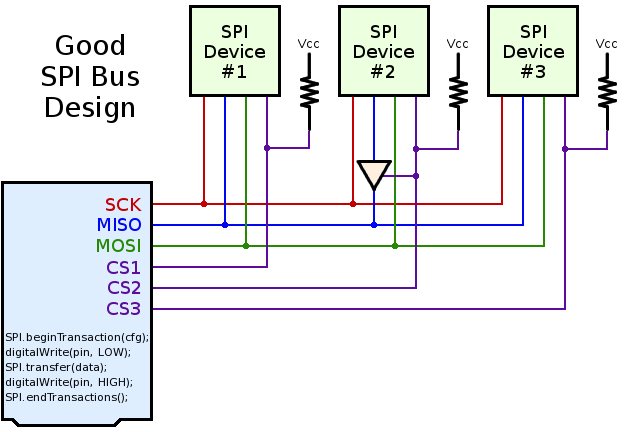
The other two lines in a basic 4-wire SPI master are for sending and receiving data: the MOSI (Master Out Slave IN) line is for the master to communicate to the slave, the other line is MISO (Master In Slave Out) which carries messages from the slave to the master. Both lines operate simultaneously, allowing communication in both directions simultaneously (full duplex).
SPI has no addressing scheme (such as with I2C). SPI comes in several variations, with some SPI chips featuring multiple MISO and MOSI (I/O) lines, all controlled by one clock, but allowing for more throughput. Operation is fairly simple. When the master wants to speak or listen to Slave_1, the SPI master pulls the SS_1 pin low (termed “active low”) and Slave_1 begins sending or receiving in synchronization with the shared clock line to the master. All other slaves are ignored.
SPI is efficient and easy to set up if there is one master and one slave. SPI has 3 registers: A Control Register (SPCR), a Status Register (SPSR), and a Data Register, (SPDR). SPDR is a Read/Write register; to send data out to MOSI, write to SPDR. To receive data that was put into SPDR in the last clock cycle as an MISO, read SPDR. Some junk data may need to be read or written to SPDR to start the clock in a set-up where only one-way communication is being executed.
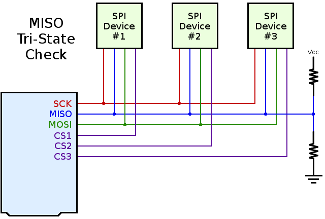
Additional tips: Test your SPI to make sure that the MISO pin is disconnecting properly when the SS is not selected. Check the MISO by connecting two 10K ohm resistors as shown in Figure 2. To test for a good tristate MISO, disable all the SPI chip selects, breadboard two 10Kohm resistors as shown in Figure 2, then measure MISO with a voltmeter. If the selects are truly off, then the MISO signal should read half of Vcc. If you see a logic level high (usually 3.3V or 5V, depending on your board) or if you see close to zero volts, you need a tristate buffer (e.g., 74AHC1G125), which acts like a valve to turn on/off the current flow. A tristate buffer is a bus buffer gate with a 3-state output.
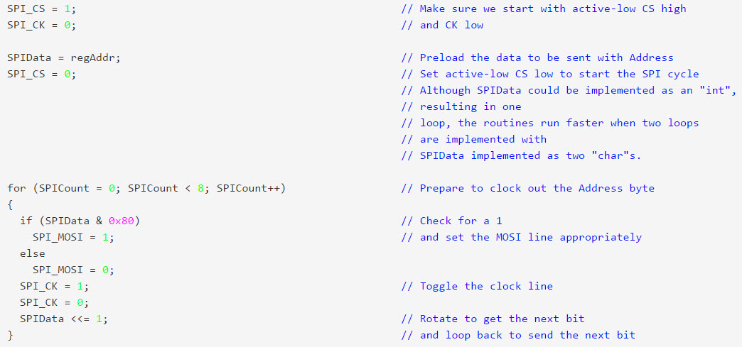
Up to now, the conversation has been mainly about the hardware trappings of SPI. Recall that SPI has no set protocol. SPI is not automatically going to set itself up and start communicating with a slave device. SPI application code is rather clear cut, and many development boards have SPI code available in the form of libraries (for example Arduino.) Figure 3 shows a very clearly commented section of code for a simple single-byte transfer using SPI from Maxim Integrated’s David Fry.
[i] Wikipediahttps://en.wikipedia.org/wiki/Serial_Peripheral_Interface_Bus
Leave a Reply